
Where I illustrate how to develop and debug code on the ATtiny13A on a Linux computer (Raspberry Pi) using the Microchip Snap, bloom and avr-gdb.
Sources#
The code for this article and other articles on the ATtiny13A can be found in the ATtiny13A repository.
Introduction#
As mentioned previously, I’ve moved from a multi-platform approach to using a Raspberry Pi (RPi) for my development system. I use it as a headless system, meaning, I connect to the RPi using ethernet or wireless from my Mac. All code editing occurs in VS Code on my Mac, while all debugging is performed via the terminal. Both VS Code and the terminal are connected via SSH to the RPi.
I load and debug code on the ATtiny13A microcontroller using low-cost debugWire interface board, called the Microchip Snap. The Microchip SNAP is an $11 board which supports debugWire, a debugging and uploading interface to an AVR microcontroller. It is supported by tools such as avrdude and Bloom.
Parts List#
This parts list is the minimum required to begin development. I referenced Digikey as that is my supplier, please use a supplier of your choice.
| Manufacturer Part Number | Manufacturer Name | Description | Requested Quantity | Digi-Key Part Number | Unit Price | Extended Price | Datasheet |
|---|---|---|---|---|---|---|---|
| SC0022 | Raspberry Pi 3B | SBC 1.2GHZ 4 CORE 1GB RAM | 1 | 2648-SC0022-ND | $35.00000 | $35.00 | Link |
| K104K15X7RF53H5G | Vishay Beyschlag/Draloric/BC Components | K 50V 100NF 10% X7R BULK GREEN A | 5 | 56-K104K15X7RF53H5G-ND | $0.80000 | $4.00 | Link |
| 4539 | Adafruit Industries LLC | HALF-SIZE BREADBOARD WITH MOUNTI | 1 | 1528-4539-ND | $5.00000 | $5.00 | Link |
| ATTINY13A-PU | Microchip Technology | IC MCU 8BIT 1KB FLASH 8DIP | 5 | ATTINY13A-PU-ND | $1.13000 | $5.65 | Link |
| PG164100 | Microchip Technology | MPLAB SNAP DEBUGGER | 1 | PG164100-ND | $11.68000 | $11.68 | Link |
| 1957 | Adafruit Industries LLC | JUMPER WIRE M TO M 6" 28AWG | 1 | 1528-1967-ND | $1.95000 | $1.95 | Link |
| BBP-32701 | Bud Industries | BREADBOARD POWER 3.3V AND 5V | 1 | 377-2647-ND | $6.30000 | $6.30 | Link |
Note: total comes to $69.58 for this ATtiny13A minimum parts list.
In addition to the parts above, two USB cables are needed:
- USB A to micro-USB for the Microchip SNAP
- USB A to USB A for the Bud Power Supply or a USB to 2.1mm DC Booster Cable - 9V
Setup#
If you are setting up a RPi, for the first time, you will need to connect via a terminal session. You will want to open an SSH terminal session. Once the RPi has been setup with the operating system (Trixie), you may follow the steps below.
These steps are required to setup a debugging workflow. Copy and paste the text from each block then hit return. These actions will take several minutes.
1. Software Installation (Terminal Session)#
The instructions below assume a Raspberry Pi, running Trixie. To setup Trixie, follow these instructions through to “Step 2 Connect via…”. I recommend using a standard terminal session (not Raspberry Pi Connect) for the next steps, for example, using macOS Terminal or Windows Command (bash shell). I use ghostty, (and love it and highly recommend it).
Update to the latest OS software.
sudo apt update && sudo apt full-upgrade -yInstall the tools, the AVR toolchain and the repository
sudo apt install wget git -y &&
sudo apt install gcc-avr binutils-avr avr-libc gdb-avr avrdude git tio tree -y &&
git clone https://github.com/lkoepsel/ATtiny.git
Install bloom along with gdb-dashboard for debugging
wget https://github.com/bloombloombloom/Bloom/releases/download/v2.0.0/Bloom-headless-2.0.0-Linux-aarch64.deb
sudo apt install ./Bloom-headless-2.0.0-Linux-aarch64.deb -y

wget -P ~ https://github.com/cyrus-and/gdb-dashboard/raw/master/.gdbinit

mkdir -p ~/.gdbinit.d
cp ~/ATtiny/docs/dashboard/avr_modules.py   ~/.gdbinit.d/
cp ~/ATtiny/docs/dashboard/avr_layout.gdb   ~/.gdbinit.d/
cp ~/ATtiny/docs/dashboard/avr_connect.gdb  ~/.gdbinit.d/
cp ~/ATtiny/docs/dashboard/avr_commands.gdb ~/.gdbinit.d/
cp ~/ATtiny/docs/dashboard/avr_autostart.py ~/.gdbinit.d/
cp ~/ATtiny/docs/dashboard/avr_settings.gdb ~/.gdbinit.d/
cp ~/ATtiny/docs/dashboard/gdbearlyinit     ~/.gdbearlyinit

cp ~/ATtiny/env.dev ~/ATtiny/env.make
cp ~/ATtiny/bloom.dev ~/ATtiny/bloom.yaml
2. Connect to the ATtiny13A#
Insert your ATtiny13A into your breadboard. You will then need to make connections to it via a cable from the SNAP.
Minimal Working Circuit#
- Connect VCC (pin 8) to your power supply (2.7-5.5V)
- Connect GND (pin 4) to ground
- Add 100nF decoupling capacitor between VCC and GND
ATtiny13A Pinout#
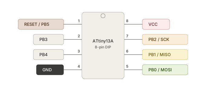
ATtiny13A Pinout
ATtiny 13A Connections for SNAP SIL#
| Snap SIL | Signal/Adapter | Wire Color | 13A Pin |
|---|---|---|---|
| 1 | N/C | none | N/C |
| 2 | VTG | Red | 8 |
| 3 | GND | Black | 4 |
| 4 | MISO | Yellow | 6 |
| 5 | SCK | Orange | 7 |
| 6 | RESET | Brown | 1 |
| 7 | MOSI | Green | 5 |
| 8 | N/C | none | N/C |
Your wire color might be different, however, confirm the connections closely from the SIL (single in-line connector) and the DIP pins.
Here is my setup. I used a AVR ISP Breadboard Adapter from Adafruit, which made the connection from the Snap SIL connector to the ATtiny13A much easier. Using the adapter, I connect 6 wires from the Snap to the breadboard like this:
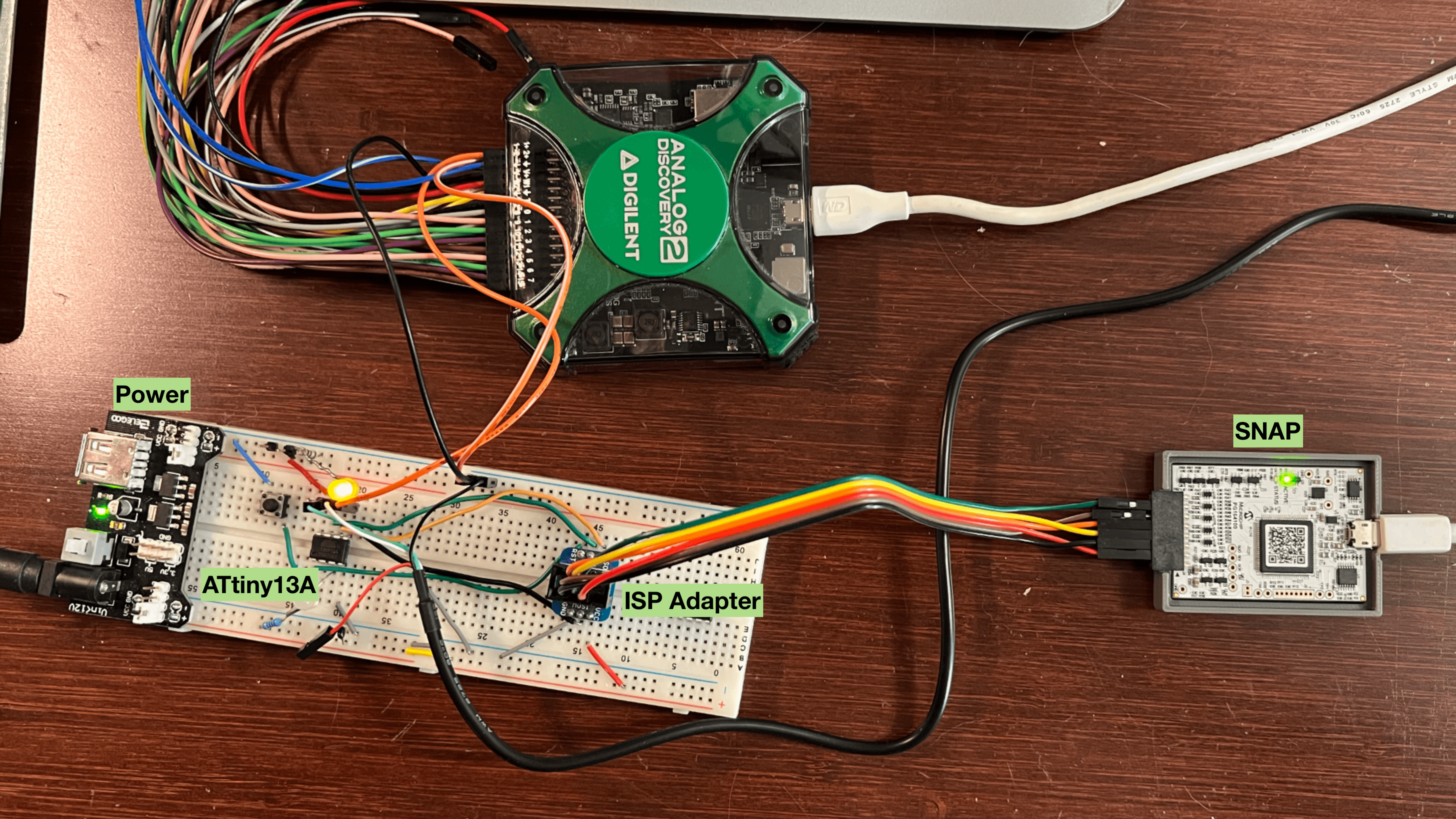
Breadboard with ATtiny13A and Snap connected
Debugging Process#
A simple overview is start bloom, start avr-gdb, begin to debug, edit the errors, reload and repeat! Bloom provides a complete full-cycle method to run-edit-reload a target, which is fantastic! Let’s begin.
1. Start bloom#
You will want to start bloom before you start avr-gdb. Bloom doesn’t require a lot of attention, however, you will want to be able to view the window easily, as it will indicate if the connection with the target is broken. I typically start it in my first tab in my terminal program. Make sure you start bloom in your project folder, as it will need to find the bloom.json file.
cd ATtiny
bloom # the default config is using the SNAP
2. Run avr-gdb#
In the main window (in my second tab), preferably full-height, in the same folder as your makefile and source. You will need to have run make complete to have a loadable main.elf file prior t to starting avr-gdb.:
cd examples/asm_blink
make complete
avr-gdb main.elf
# to begin running the program (c as in continue)
c
# to stop execution
Ctrl-C
# to set a breakpoint, at a function name or set a lineno
br functionname | lineno
Example Display (initial)#
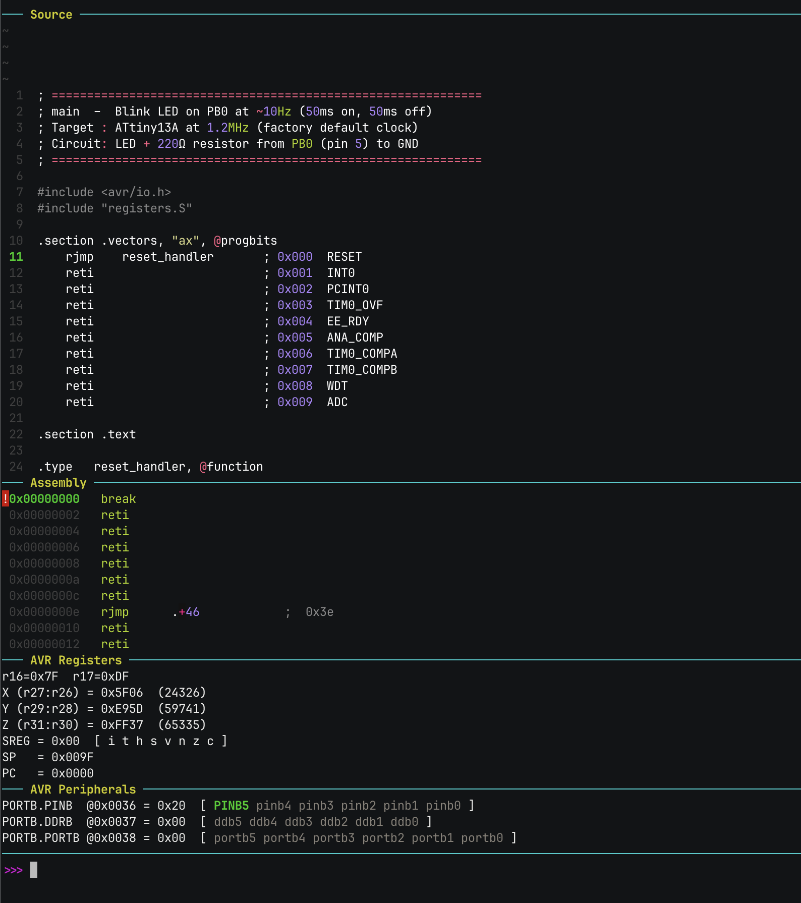
avr-gdb screen using Bloom in asm_blink, initial screen
This screenshot is of avr-gdb, immediately after executing avr-gdb.
Example Display (after Ctrl-C)#
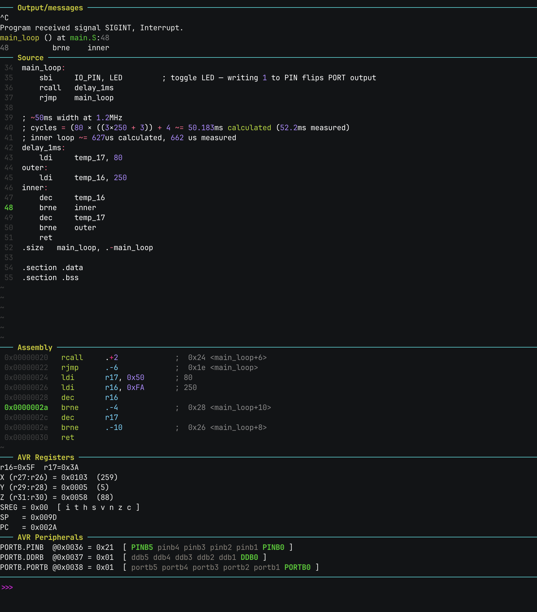
avr-gdb screen using Bloom in asm_blink after Ctrl-C to stop execution
This screenshot is of avr-gdb, immediately after executing a Ctrl-C command. The big change is in the PORT values, notice DDB0 is green and upper-case, this means it is high (1) and the pin is an output. And with PORTB0 also high, the LED will be lit.
3. When you want to upload code#
Ok, you’ve found a bug, edited your code and now you want to reload it on to the ATtiny13A… Do all of this in the comfortable confines of avr-gdb.
# Ctrl-C to stop the processor and return control to the console
(gdb) cll # this will compile-link-load your file back on to the ATtiny13A
(gdb) c # begin execution to determine if fix worked
The cll command comes from the .gdbinit file and performs the following:
- make - recompiles necessary files to ensure the latest version
- load main.elf - the magic step where bloom loads the program on the ATtiny13A
- list - list the program again
- refresh - clean up tui display
Screen Setup#
When I’m debugging using avr-gdb/bloom, I will have two half-screen (vertical) windows open. On the left half of the screen, I have VS Code for editing the program. On the right half of the screen, I have my terminal program (ghostty), with two tabs, the one used most often shows avr-gdb, while the other tab is used to start bloom. My steps are the following, edit the code in VS Code, switch to avr-gdb and run cll which is a compile-link-load of main.c, then press c to start the program.
Happy Debugging!