Where I use a detailed analysis of the ATmega328P datasheet to develop C code using the C toolchain. Yes, another look at the blink program!
Sources#
- Microchip AVR ATmega328P Go to this page for the datasheet, you will need it.
- Definitive UNO pinout, see below
- avr-libc Standard AVR C Library.
Introduction#
You’ve installed the tool chain, you’ve tested it and added automation. This means you are now ready to begin the process of learning how to program an embedded microcontroller! You might have thought, that was what you were doing with the Arduino. Not quite, you were programming a specific embedded microcontroller board with a specific programming framework.
We are going to start from “bare metal”, which means there is no existing code on the microcontroller and what you write is the only code that exists! Well, there will be a small framework which we will use called avr-libc. It is more akin to the C standard library which you would find on your laptop.
We will do this for several reasons:
- It is the best way to learn how to write embedded software and to learn how to write in C.
- It allows you to reduce the code to the bare essentials that you need, shrinking the space required for the code. Less code, smaller device and lower costs of implementation!
- Its fun!
Outside of the tool chain, which you have already installed, the megaAVR Data Sheet (you will need to click on Download Data Sheet) will be extremely important. We will continue to use an Arduino UNO board as it will provide the hardware necessary for a target embedded microcontroller board. (As compared to asking you to wire one using a breadboard and bare chips. We’re not barbarians!)
Blink#
Yes, we are going to start with blink, the “Hello World” of embedded processors. Using blink will give us an immediate reason to begin exploring the ports on the ATmega328P. And it will provide us positive feedback when we are successful!
Find the LED#
To start we need to look at the pin-out of the Uno. Notice the light yellow tabs around the board, with a nomenclature of PBn, PCn or PDn with n ranging from 0-7). These are the names of the pins according to the Datasheet. These are the ones that matter to us. There will be other names which we can also consult, however these are the canonical names. Where P stands for Port, a letter B, C or D, indicating which port and a number indicating the specific pin on that port. So PB3 is Port B, pin 3 and PD7 is Port D, pin 7.:
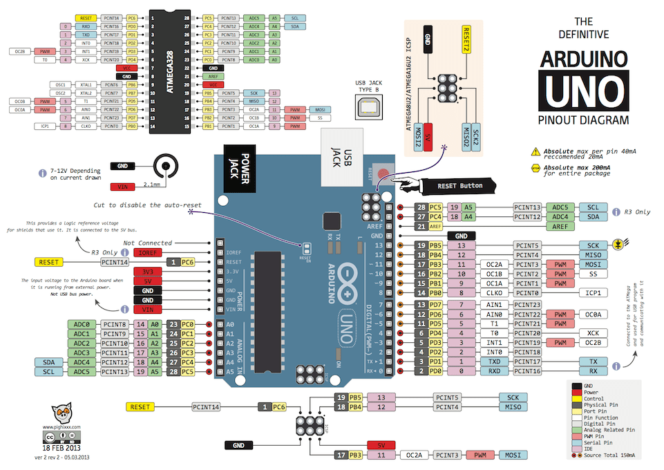
Arduino Uno Pinout
If we look for the LED symbol, we’ll find it on Arduino pin 13 or our pin, PB5. From here on, we know that the built-in LED is on PB5. This is the pin we want to light up, which means we want PB5 to be an output pin and we will write a value of 1 to the pin to light the LED and 0, to turn the LED off.
Datasheet#
Go to section 14. I/O-Ports, page 84 in the datasheet. (Please make sure you have the latest one, mine is dated 2020 Microchip Technology) This section will advise us how to turn on a pin. The most important paragraph is this one, the third paragraph on page 84:
“Three I/O memory address locations are allocated for each port, one each for the Data Register – PORTx, Data Direction Register – DDRx, and the Port Input Pins – PINx. The Port Input Pins I/O location is read only, while the Data Register and the Data Direction Register are read/write. However, writing a logic one to a bit in the PINx Register, will result in a toggle in the corresponding bit in the Data Register.”
Breaking this paragraph down, there are three address locations for each port (x can be B, C, or D based on the Port in question):
- Data Register (PORTx) - R/W and contains the output value of the port
- Data Direction Register (DDRx) - R/W it is 1 for output and 0 for input
- Port Input Pin (PINx) - R only, contains the external value on that pin (0 if GND or 1, if close to 5V)
For the purposes of this discussion, we’ll only worry about the first two Registers.
So it sounds like we need to set a direction for a pin and we need to set the value on a pin to accomplish what we want. Let’s read (ok, scan) a bit further and there is greater detail on the next page:
Configuring the Pin#
“Each port pin consists of three register bits: DDxn, PORTxn, and PINxn. As shown in ”Register Description” on page 100, the DDxn bits are accessed at the DDRx I/O address, the PORTxn bits at the PORTx I/O address, and the PINxn bits at the PINx I/O address. The DDxn bit in the DDRx Register selects the direction of this pin. If DDxn is written logic one, Pxn is configured as an output pin. If DDxn is written logic zero, Pxn is configured as an input pin. … If PORTxn is written logic one when the pin is configured as an output pin, the port pin is driven high (one). If PORTxn is written logic zero when the pin is configured as an output pin, the port pin is driven low (zero).”
And when we go to page 100, as referenced in the second sentence above we see this:
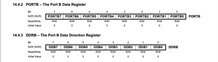
ATmega328P Port B Registers
OK, we think we’ve got it. Let’s try to write a little code and see what happens!
Coding#
We are using avr-gcc as our compiler and the tool chain includs avr-libc which is a small C library which will help us program for all of the AVR family. For now, take it on faith that the library sets up the same names which we see in the datasheet. So we don’t have to worry about specific addresses, we can simply use the names in the datasheet. However it does mean we’ll want to include the reference header in our program:
#include <avr/io.h>There is also a note following section “14.2.1 Configuring the Pin” and it calls out an instruction “SBI” for setting a specific bit on a port. The avr-gcc compiler has created a macro for this called _BV(n) which stands for Bit Value. This allows us to write code that looks like this:
DDRB |= _BV(DDB5); // Set bit 5 of the Data Direction Port B
A description of the code, “|=” means OR the value on the right with the value on the left and _BV(DDB5) (the value on the right) means set the specific bit according to DDB5. Which in our case looking at the table above, is the Data Direction Register B, bit 5. And when this instruction is executed, that specific pin (connected to the built-in LED) will be configured as an output. Excellent!
This also implies that if we were to execute this instruction:
PORTB |= _BV(PORTB5); // Set bit 5 of Port 5
It would set that pin high and light the LED!! We are almost there!
Note: There is another command which might be interesting as well:
sfr &= ~(_BV(bit)); // It clears the bit, it is an inverse of |= _BV(bit)
In the documentation, sfr stands for special function register such as DDRB or PORTB.
avr-libc#
Just like with the Arduino, we need a delay of some sort to cause the LED to blink. Maybe it is time to see if we can find a pre-existing function from our avr-libc library as compared to writing something ourselves! Let’s go specifically to the Library Reference and scan the header files.
Convenience functions for busy-wait delay sounds like something we might want. Scanning the page, we see “Perform a delay of _ms milliseconds…”, yes! that sounds right. We’ll need to do two things, add the library and add the command:
#include <util/delay.h>
_delay_ms(double __ms);
There is no predefined template like there is with the Arduino. We’ll have to create one for our program. We’ll want two areas, a setup area and a infinite loop area, very similar to what is done on the Arduino. It will also have to be a standard C program. Here is our standardized template going forward:
// Comment on the program
// Definitions, headers, etc
#include <>

int main (void)
{
	// Setup area

	// Infinite loop
	while(1) {
	}
}
Let’s layout the entire program, here:
// Our own blink program
#include <avr/io.h>
#include <util/delay.h>
int main (void)
{
	// Set the built-in LED PB5 to be an output
	DDRB |= _BV(DDB5);
	// Enter an infinite loop
	while(1) {
		// turn LED on, then wait
		PORTB |= _BV(PORTB5);
		_delay_ms(1000);

		// turn LED off, then wait
		PORTB &= ~(_BV(PORTB5));
		_delay_ms(1000);
	}
}
Test the code!#
The simplest thing to do is to copy and paste the code above into the led.c file you used in setting up the tool chain. The two programs are very similar, however I simplified the code above just a bit more.
Specific instructions if you aren’t quite sure:
- In the command line (Terminal on Linux/macOS and Git Bash in Windows), go to the folder PureC/led
- In this folder, there will be two files, led.c and Makefile. The latter comes from 3. Automate using a Makefile in Setup (All Platforms).
- Copy and paste the code above into led.c file, the code above needs to replace all of the existing code in the file.
- Make sure your Uno is connected to computer
- Run “make flash” in the command line Watch your led blink!
I recommend changing the values in the delay statements and rerunning “make flash”, to ensure you know you are downloading new code.
What have we learned?#
- Well, the above blink program was “188 bytes of flash written” and when we use the Arduino to perform an identical program, the Arduino “uses 924 bytes of program storage space.”
- We’ve learned the importance of the AVRmega data sheet and we began to understand how to use the data sheet.