Where I continue to use the Labrador to test the PWM functionality of the ESP32.
Sources#
- Makeability Lab Lesson 3: Fading an LED with PWM
- ESP32-GetStarted: PWM
- MicroPython PWM
- Espressif: LED Control
Background#
We continue to use the Labrador to evaluate how the HUZZAH32 operates. In this case, we’ll dive into how to use the H/W PWM functions as compared to doing it in software.
The PWM functionality is called LEDC by Espressif, the manufacturer of the ESP32. This stands for LED control and it works quite well for fading, controlling brightness etc of an LED. That said, we can understand it far better if we observe the signals using the Labrador.
The source above, Makeability Lab, has an outstanding explanation of the ESP32 PWM. I strongly encourage reading it. We’ll continue to make references to it throughout this discussion.
First Pass#
The machine.PWM capabilities seem sparse as compared to the ESP32. On initial reading, the following parameters are available:
dir(machine.PWM)
['__class__', '__name__', '__bases__', '__dict__', 'deinit', 'duty', 'freq', 'init']
I wasn’t able to find an example using init, so I did a little searching. And found the GitHub:esp32/machine_pwm where there was a commit of:
ESP32 has 16 PWM channels with 8 separate timers, but current PWM implementation
forces user to share single timer between all channels. This commit
allows to use all 8 timers and does not break backward compatibility.

API additions:
- PWM initializer takes two new optional keyword arguments:
	`pwm.init(..., timer=0, speed_mode=PWM.HIGH_SPEED_MODE)`
- PWM class defines two new constants:
	`PWM.HIGH_SPEED_MODE` and `PWM.LOW_SPEED_MODE`
Note: Attempted to set timer=0…failed. Continued to investigate and found Issue: 3608 has yet to be merged. The earlier code was for an old branch of MicroPython_ESP32. Continued to investigate and found several desires to increase the number of timers available for PWM with ESP32, however, all point back to this same GitHub issue. Sigh.
I’ll use Pin 21 as it is easily accessible and easily seen on the chip. It is the last chip on the “long side” (long side has pins RST - Pin 21) and the 21 can be seen by the mounting hole.
Note: I keep PinTest renamed to main.py on the board. This means anytime I press Reset, PinTest begins to run. This makes it very easy for me to confirm that I am connected to the correct pin and it is working properly. In this case, I entered 21 for pin to test and watched the pin go HIGH, LOW, and PULSE given 1, 2, and 3 for tests.
#
- In Serial Monitor, lets do the most simple test identifying Pin and frequency:
from machine import Pin, PWM
p21 = PWM(Pin(21), freq=5000)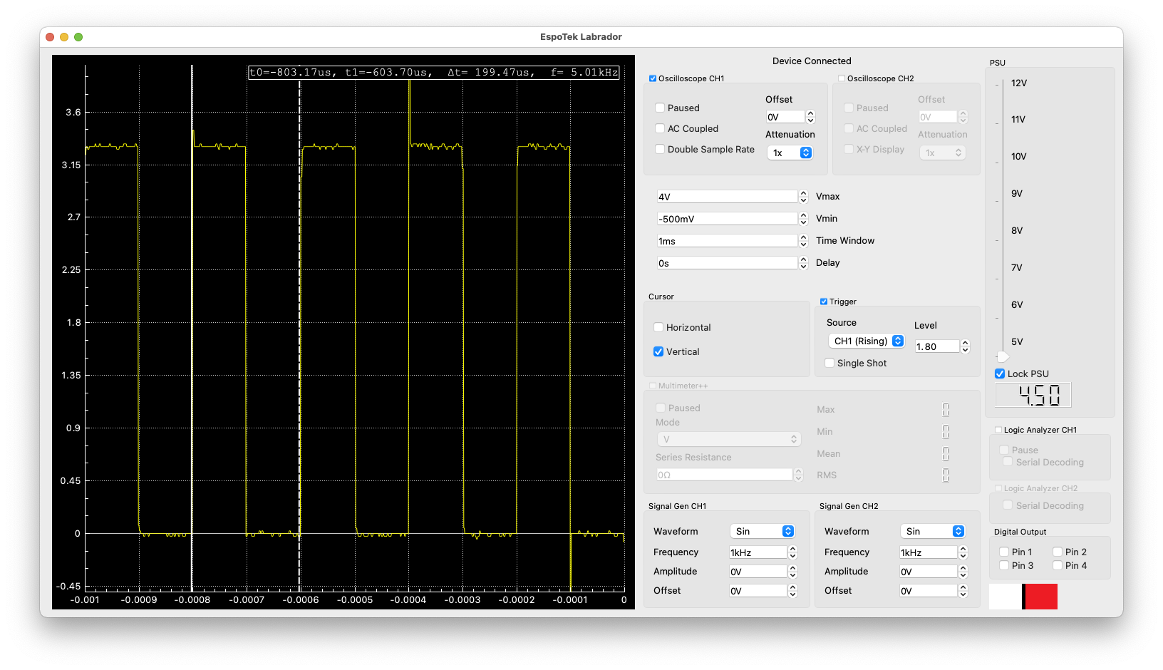
Labrador showing Pin21 with 5kHz signal
- Duty ranges from 0-1023, which means a duty cycle of 25% is approximately 250, so let’s add that. And yes the width of the on pulse was 50us, while the off pulse was 150us. (No image for this.)
p21 = PWM(Pin(21), freq=5000, duty=250)- We have two channels on the Labrador. Using a blue wire, connect Oscilloscope CH2 to pin 14 (short side, 3rd pin up.) In the image, the blue signal is CH2 and it sits right on top of CH1, making it hard to see.
p14 = PWM(Pin(14), freq=2500)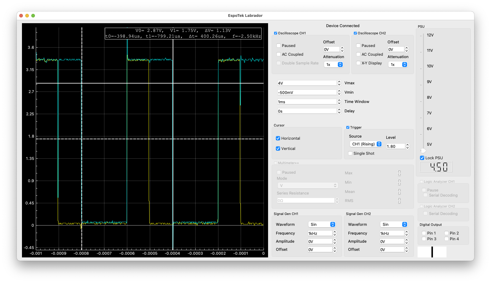
Labrador showing Pin14 with 2.5kHz signal
- Attempted to have two different frequencies on two pins and that didn’t work.
from machine import Pin, PWM
p21 = PWM(Pin(21), freq=5000)
p14 = PWM(Pin(14), freq=3300)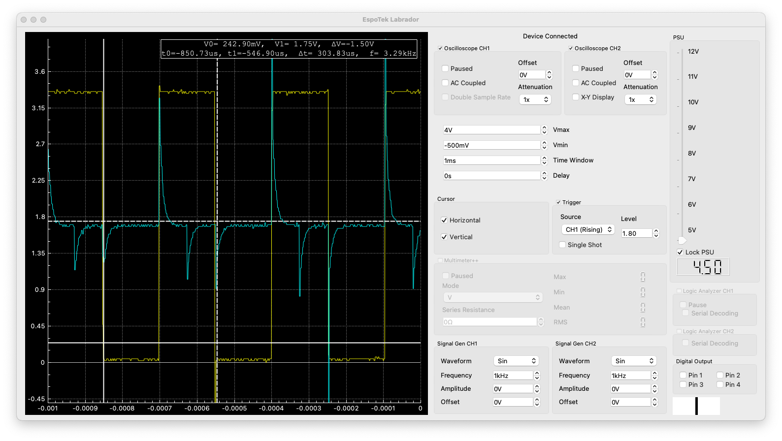
Labrador showing two pins, two frequencies
p14.deinit()So the bad news is, on the ESP32, MicroPython PWM is extremely limited considering the power of PWM on the ESP32. The good news is, we were able to find that out pretty quickly using the Labrador!