Where I begin to develop code in C on the RP2040.
Sources#
- Raspberry Pi Pico SDK: Raspberry Pi Pico SDK
- Raspberry Pi Pico Pinout
- Getting Started with Pico
- Shawn Hymel on Digikey
Introduction#
I like using Forth to develop code on embedded microcontrollers, however at times, I’ll have a project that requires a more supportive framework. In this case, C is a superior choice if I need the execution speed of Forth and the framework of microPython. This requires a significant investment in building the tools required and skills to use those tools, to develop in C.
In a series of entries, I will discuss building the tools for C to develop code for the RP2040 on three distinct platforms, Linux, Mac and Windows. I’ll follow the documentation and begin with the simple example, blink then serial output with Hello World and close with a command line debugging approach.
I won’t use Visual Studio Code as the Pi Foundation and many others advocate. I have found Code introduces as many problems as it attempts to solve and I don’t care for its interface. I’ve found its better to understand the under-lying tool gdb than abstract it away with the clutter of Visual Studio Code. If you develop code for living, by all means, use the tool of professionals, an IDE. If you are experminting/learning/hacking, focus on the project not learning how to use an IDE.
To begin#
The documentation for the RP2040 and the Pico is outstanding. My goal isn’t to replace the documentation, however, my goal is to augment the documentation such that one might be successful, sooner rather than later. For even as outstanding as the documentation is, there are a few “gotchas”.
I’ll follow the “Getting Started with Pico” pdf (known as the Guide from here on.) referenced above dated as of 23 June, 2021. It is extremely important to use the latest one, as they have continued to refine and update its contents. As I said before, I’ll do an entry for each platform, Linux, Mac and Windows. I will not (as of this time), worry about the Rasberry Pi OS as it seems well-covered.
Important Hardware Requirements#
While the initial setup is simple, a Raspberry Pi Pico and a USB micro-cable, you will very quickly need a few more items:
- Second Pico to use as a PicoProbe for debugging
- FTDI breakout board and cable for console I/O from target system i,e; Adafruit, Sparkfun
- A breadboard which can contain both Pico’s (optional, however a pain without it)
Chapter 1. Quick Pico Setup#
The focus on this chapter in the Guide is on the Raspberry Pi. For Linux, I found that its best to install all of the required applications, so that you don’t have to bounce between installations and development. I installed the following which are all of the Linux programs required to develop: (This was executed on a fresh Linux system, Kubuntu, some of the applications might already be installed on your system.)
sudo apt install git
sudo apt install cmake gcc-arm-none-eabi build-essential
# OpenOCD will require pkg-config (not indicated in the Guide...)
sudo apt install pkg-config
sudo apt install minicom
sudo apt install gdb-multiarch
sudo apt install automake autoconf texinfo libtool libftdi-dev libusb-1.0-0-dev
Chapter 2. The SDK#
Add the content from Raspberry Pi on GitHub. Pretty easy step, make sure you are creating a folder structure that has pico at the root along with two subfolders, pico-sdk and pico-examples. It’s easy to get lost.
cd Documents
mkdir pico
cd pico
git clone -b master https://github.com/raspberrypi/pico-sdk.git
cd pico-sdk
git submodule update --init
cd ..
git clone -b master https://github.com/raspberrypi/pico-examples.git
Chapter 3. Blinking an LED in C#
In this step we begin to create code. Be sure to set the environment variable PICO_SDK_PATH! I use an absolute path as I experienced issues with using a relative path. On the make command “j4” represents the number of threads to use to develop using make. Typically it matches the number of cores you have on your system. If you know that number (such as many high-end PC’s or Macs have 8), you can increase it. Otherwise, stick to 4.
export PICO_SDK_PATH=/home/username/Documents/pico/pico-sdk
cd pico-examples
mkdir build
cd build
cmake ..
cd blink
make -j4Installing code on the Pico#
Start with an disconnected Pico and to set the Pico in USB mode:
- Hold down the BOOTSEL button on the Pico board
- Plugin the USB cable
- Release BOOTSEL
If you did it properly, RPI-RP2 will show up as a USB drive. If not, try again. Once the drive shows up, drag the file blink.uf2 to RPI-RP2. It will disappear from your file manager window and the code will begin to run on the Pico. Woot!
Watch the LED blink for a moment and then go on to the next step.
Making PICO_SDK_PATH Permanent#
You will want to add the line “export PICO_SDK_PATH=/home/username/Documents/pico/pico-sdk” to your shell .rc file so that it doesn’t cause issues later on. On Linux, its typically “.bashrc” or “.zshrc” in your home folder. Add the line at the end of the file.
Hint for Easier Installation of Code#
If all of this worked, the most important comment in this chapter is 3.2.4: “To enter BOOTSEL mode on your Raspberry Pi Pico, and load code over USB, you need to hold the BOOTSEL button down, and then reset the board in some way. You can do this by unplugging and plugging the USB connector, or adding an external button to pull the RUN pin to ground. [emphasis mine]”
I’ve found you don’t even need a button, you can do the following:
- Plug a wire into Pico’s pin 30 on the breadboard
- Press and hold BOOTSEL
- Connect the wire to GND then disconnect from GND
- Release BOOTSEL and the board will appear as a drive
Once you have done this, you may also use the command line to copy:
cp blink.uf2 /media/username/RPI-RP2If the command doesn’t work, make sure Automount is setup for USB drives (in System Settings) or make sure you select the drive in the File Manager.
All of this tends to work the first time, now we’re getting into treacherous waters.
Chapter 4. Saying “Hello World” in C#
In this chapter, the directions allow for either USB or UART for serial communications. My strong recommendation is to go UART, using the FTDI cable referenced above and ignore the USB connection. You won’t be able to debug any USB communication via the SWD method below. I won’t be using the USB connection going forward.
Follow the instructions, they work well. To use the UART connection, use the folder serial in the Hello_World folder and hello_serial is the file name in build/Hello_World/serial.
In the first step above, you installed minicom as the serial program, its well-supported and has little to no issues. To test minicom with the Pico board, you might have to use sudo as the serial ports require root access:
sudo minicom -b 115200 -D /dev/ttyACM0This approach is sub-optimal. After considerable searching I was able to find this solution on github for openocd.
Solution for sudo on serial ports#
For this step, I recommend plugging in both USB serial cables at this time. This fix is easy to implement and doing so for both cables, eliminates an extra step later. Steps to follow: (actual steps and output below)
- Run dmesg to determine idVendor and idProduct of the two USB interfaces
- Use sudo and your favorite editor to create a file: “/etc/udev/rules.d/50-myusb.rules”
- Using the idVendor and idProduct numbers, create two lines in the file using this format (replacing the numbers shown with your numbers):
SUBSYSTEMS==“usb”, ATTRS{idVendor}==“2e8a”, ATTRS{idProduct}==“0004”, GROUP=“plugdev”, MODE=“0660”, TAG+=“uaccess”
- Save and close the file then restart your system.
# use dmesg to determine idVendor and idProduct
# be sure to use the right USB devices (such as usb 1-1 and usb 1-2 below)
dmesg
# ...
[62603.487834] usb 1-1: New USB device found, idVendor=0403, idProduct=6001, bcdDevice= 6.00
...
[62603.492032] usb 1-1: FTDI USB Serial Device converter now attached to ttyUSB0
...
[62607.143187] usb 1-2: New USB device found, idVendor=2e8a, idProduct=0004, bcdDevice= 1.00
...
[62607.145394] cdc_acm 1-2:1.0: ttyACM0: USB ACM device
# ...
sudo nano /etc/udev/rules.d/50-myusb.rules
SUBSYSTEMS=="usb", ATTRS{idVendor}=="0403", ATTRS{idProduct}=="6001", GROUP="plugdev", MODE="0660", TAG+="uaccess"
SUBSYSTEMS=="usb", ATTRS{idVendor}=="2e8a", ATTRS{idProduct}=="0004", GROUP="plugdev", MODE="0660", TAG+="uaccess"
# save the file then reboot your system
Chapter 5. Flash Programming with SWD#
Now we are getting into the fun stuff!!!
Appendix A: Using Picoprobe#
Before we go forward, we need to make a side trip to Appendix A as we are not using the Raspberry Pi as our debugger. Which means we’ll use a second Pico to be a PicoProbe.
Solder Wires to Target Pico#
You will need to solder wires to the Pico serving as the target Pico. Solder short wires to SWDCLK, SWDIO and GND at the end of the Pico.
Install firmware to make a Pico a PicoProbe#
cd ~/pico
git clone https://github.com/raspberrypi/picoprobe.git
cd picoprobe
mkdir build
cd build
cmake ..
make -j4
Follow the steps above to copy the picoprobe.uf2 file to the Pico serving as a PicoProbe.
Install OpenOCD#
I assume you have already installed the requirements in Chapter 1 above. This step is installing the specific version of openocd which can use the PicoProbe on Linux. Note the configure step below, it is quite different than the configure step using the Raspberry Pi. Be sure to use this one or the PicoProbe won’t be enabled as an adapter.
cd ~/Documents/pico
git clone https://github.com/raspberrypi/openocd.git --branch picoprobe --depth=1 --no-single-branch
cd openocd
./bootstrap
./configure --enable-picoprobe
# review OpenOCD configuration summary, check for Raspberry Pi Pico Probe, as in:
# Raspberry Pi Pico Probe                 yes
make -j4
sudo make install
The PicoProbe board will not need wires soldered to its SWD pins.
To wire the two boards, you will want to put them on the same breadboard and connect them per Shawn Hymel on Digikey or the Guide:
Wiring Guidance#
- PicoProbe GP2 -> Target Pico SWCLK
- PicoProbe GP3 -> Target Pico SWDIO
- PicoProbe GP4/UART1 TX -> Target Pico GP1/UART0 RX
- PicoProbe GP5/UART1 RX -> Target Pico GP0/UART0 TX
- PicoProbe VSYS to Power Rail
- PicoProbe GND to Ground Rail
- Pico VSYS to Power Rail
- Pico GND to Ground Rail
By using a long breadboard, you can mount the target Pico on one end and the PicoProbe on the other end. The Pico will get its Power and Ground from the PicoProbe, it will route its serial IO through the PicoProbe. This approach works very well!
Testing OpenOCD#
If you have properly completed the following:
- Installed OpenOCD for the PicoProbe. If this step wasn’t completed properly, you will not see PicoProbe listed when OpenOCD lists its interfaces. It is very important to install the PicoProbe version of OpenOCD, not the generic version.
- Followed the guidance above to allow serial ports to be opened without being root. If you experience connection problems, try using sudo with your openocd command. If it works, then both ports aren’t setup properly in Chapter 4.
- The wiring is correct. Not sure how to correct other than say “double check your wiring.”
Then, and only then you may continue and perform a test of OpenOCD.
5.3. Loading a Program#
Make sure you are in the correct folder then:
openocd -f interface/raspberrypi-swd.cfg -f target/rp2040.cfg -c "program blink/blink.elf verify reset exit"If all went well, you will see a long series of text and the target pico is blinking! If not, check the following:
- are you in the right folder?
- is the PicoProbe showing in the list of adapters available (the only way I see this list is openocd can’t connect to the picoprobe)?
- is your wiring correct and the wires are making good connections?
Per the last page of Chapter 5, I also recommend you edit the blink on and off times then recompile and copy back to the target Pico to confirm you have a working connection. You will be doing this quite a bit, and could use the practice. :)
Chapter 6. Debugging with SWD#
This chapter pulls it all together to create a complile/link/load/run/debug process using the RP2040 and the C SDK.
Build debugging binaries#
As the Guide states, its important to build a debugging binary to allow for greater ease and capability in the debugger. The process is similar to the original, except you add a parameter for debugging. In this case, we’ll use Hello World so we can test the serial console.
cd Documents/pico/pico-examples
cd build
cmake -DCMAKE_BUILD_TYPE=Debug ..
cd hello_world
make -j4
Using -D for CMake Options#
It doesn’t seem to be well-documented, however, one uses -D to change specific options while compiling code. As shown above “MAKE_BUILD_TYPE” will create a file with or without Debug information required by gdb. You can also use “-DPICO_BOARD” if you are using a board different than the Pico, such as “-DPICO_BOARD=adafruit_feather_rp2040”. You can see all of the options in pico-examples/build/CMakeCache.txt.
Create a Debugging Screen Setup#
We’ll want to start using best practices to accelerate our ability to develop code. In this case, we’ll want to have a debugging screen setup that works. I use the following:
- Divide the screen into a left half and right half. (In your mind, so far…)
- Open your code editor (in my case, Kate) and place it on the left half of the screen with my code under test open in the editor.
- Open a terminal window in the right half, however, shorten it so that it consumes only the top half of the right half (meaning the top right quarter of the screen). In this window, we’ll have two tabs:
- one tab will be openocd, which must remain open for it to work. We’ll leave it open and
- open another tab, which will run gdb, this is where our debugging commands will go
- In the bottom quarter of the screen, open another terminal and begin execution of “minicom -b 115200 -D /dev/ttyACM0”, this will be the console output from the target Pico.
Your screen will look similar to this:
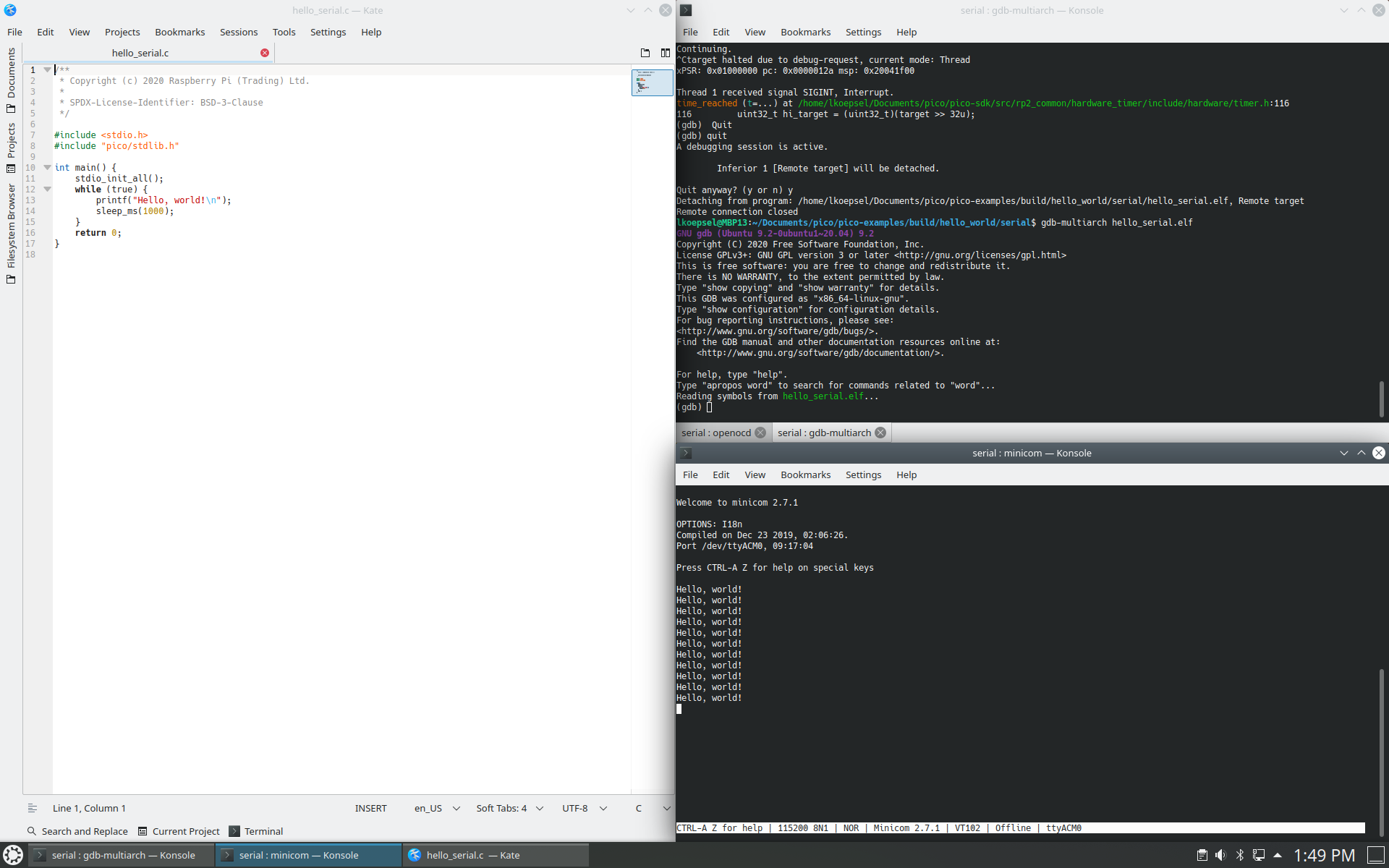
Debugging Hello_World on Linux
Once you have the three windows, open your source code in your code editor on the left then (practice these commands from the Guide to get a feel of how to start and stop your code):
#copy latest to target
openocd -f interface/picoprobe.cfg -f target/rp2040.cfg -c "program hello_serial.elf verify reset exit"

# open a debugging session in current window, this is the top quarter window
openocd -f interface/picoprobe.cfg -f target/rp2040.cfg

# open a second tab for minicom to interact with target, also in the top quarter window
# this window will be the console output from the target board
minicom -b 115200 -D /dev/ttyACM0

# open second window for gdb debugging and add it as the bottom quarter window
# this window will for debugging commands
cd ~/Documents/pico/pico-examples/build/hello_world/serial
gdb-multiarch hello_serial.elf
(gdb) target remote localhost:3333
(gdb) load
(gdb) monitor reset init
(gdb) continue
(gdb) monitor reset init
(gdb) b main
(gdb) continue
(gdb) quit
`
In my next entry, I’ll spend time on gdb and how to debug a C program on the RP2040 using this setup.