Where I go into detail as to how I develop code in CircuitPython for the omzlo FIDI board.
Omzlo FIDI#
Technical details#
- Small!: it measures 25.4mm x 22mm (1" x 0.86")
- Microchip ATSAMD21E18A 32-bit Arm Cortex M0+ running at 48MHz, with 256KB flash, and 32KB RAM
- 4MB flash for CircuitPython code and other files
- Six GPIOs, featuring SPI, I2C, UART, Digital/Analog IO, PWM, …
- 3.5mm terminal block connectors and one 4 pin QWIC/STEMMA QT connector
- 3.3V logic level, maximum 200mA
- USB micro connection to PC
- User-controlled RGB LED
Pinout#
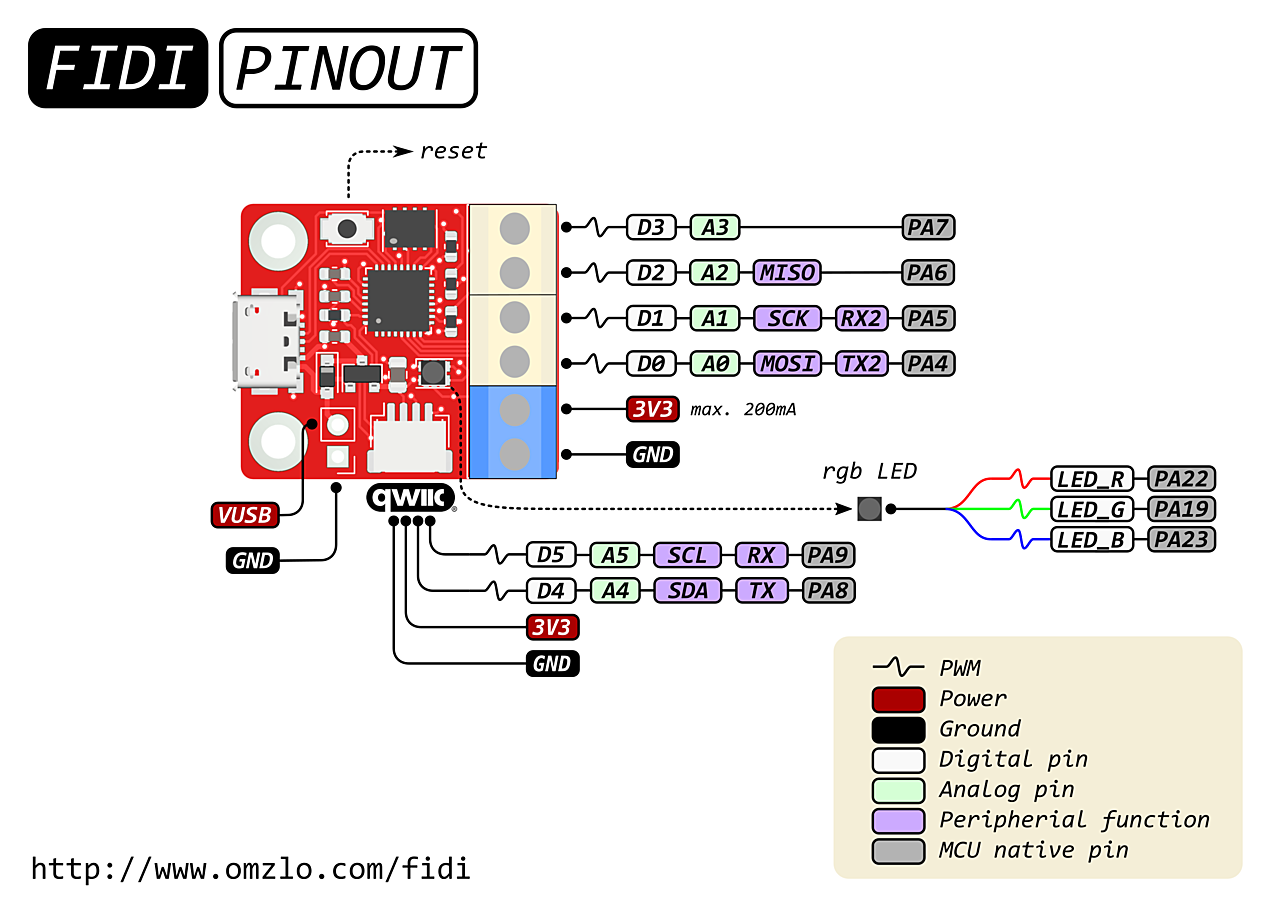
omzlo FIDI
Protoboard connected to FIDI#
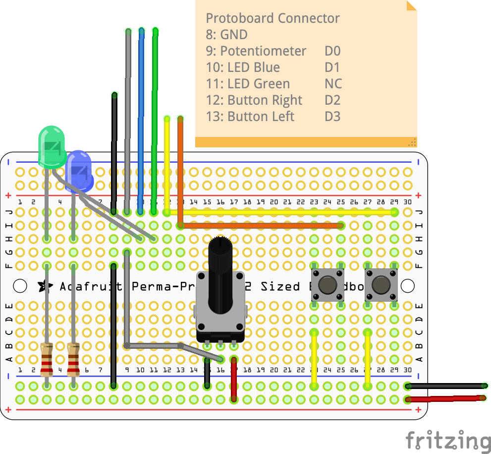
omzlo FIDI
Editing Process#
I use a lot of boards and a few different programming languages. Switching between them can be a problem, if I don’t remember the programming environment, special aspects of the language and particulars of the board. I thought it would be of value to document the CircuitPython, FIDI experience not only for myself, however, for others as well, to understand how to set up an efficient development experience.
Elements of Development#
Each board/language combination has its elements of development. It would be nice to use the same setup for each language and board, however, it isn’t practical. For example, the RP2040 boards use a very sophisticated environment involving the GCC Embedded ARM compiler, an extra RP2040 board as a hardware debugger and a complicated CMAKE process. This board, the FIDI and the language, CircuitPython are far less complex, however, there is value in automating much of the process.
For the FIDI/CircuitPython combination, here are the elements of development:
- FIDI board, ATSAMD21E18A-based board so it has an 32-bit Arm Cortex M0+ running at 48MHz, with 256KB flash, 32KB RAM and 4MB flash for CircuitPython code and other files
- CircuitPython (or MicroPython) with the CircuitPython library bundle
- Sublime Text 4 incorporating a build process
- USB cable with a micro-USB connector and a simple prototyping board with two buttons, a potentiometer, an ultrasonic transducer and connectors (optional project-specific)
I will describe each element and cover aspects of its use, importance and other criteria.
Starting with the FIDI board, I’ve added the details of the microcontroller as well as the amount of memory. These aspects are important as they serve as the foundation to determine at a minimum, the programming language. In this case, the speed and power of the microcontroller allows us to use a more simple programming environment and a scripting language such as Python. This would not be the case, if we were using the 8-bit AVR ATmega328, where we have to use C or Forth, to pull all of the possible power out of the microcontroller.
CircuitPython is a beginner-friendly, microcontroller scripting language. It abstracts much of the ARM processor’s complexity into something we can quickly understand. This simplicity does come at a cost. I was stunned to find out that certain aspects of CircuitPython (asyncio) aren’t available to this 32-bit processor with 32KB RAM and 4.25MB of flash memory…due to insufficient memory!
With the two main components determined, we then need to think about the edit/build process. For C, the build process is edit->compile->link->load, for Python is both more simple and requires a bit more work to automate. For example, the build process has several steps, load code.py onto the board as well as copy a specific set of routines into the board’s library.
The USB cable provides both serial communication and power to the board and the prototyping board supplies the interface elements required, two pushbuttons and an ultrasonic transducer.
The Process of Development#
Every project, particularly with a new board, starts the same way, blink. Its the best way to ensure the board works, you are able to create a program for the board, install it on the board etc. I always have blink available in many of my development libraries, simply to confirm to me when things stop working, that yes, the board works, my process works…my new code, doesn’t.
Step 0: Setup#
Make sure the board has the latest version of:
If this is your initial effort or if it has been a while (> 6 months), its best to update all three to ensure you have the latest code.
Step 1: Blink#
I connect the FIDI board to my computer with a USB cable, simple enough! I start my communication program, Serial and see the board in Serial’s connection window (top), double-click and nothing happens (empty window). Okay, I hit Ctrl-C and get this (bottom):
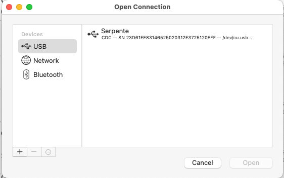
Serial's SerialConnection Window
Large Version to see detail
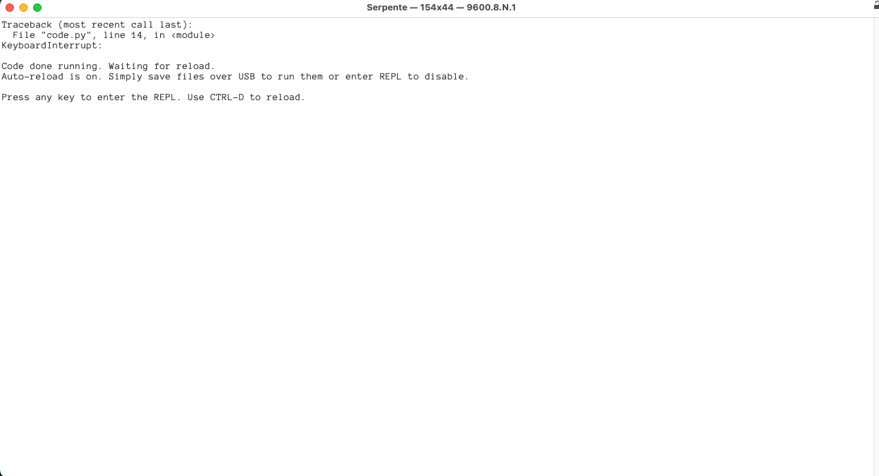
CircuitPython response from FIDI
Excellent, we have a working board and it is running CircuitPython. However, upon further investigation, I’ve found it has CircuitPython 5.0.0 installed. So I need to go looking for the latest version 8.0.0. The CircuitPython site has versions of CP for specific boards, I downloaded the Serpente version based on the FIDI documentation.
Install (both CircuitPython and Bootloader)#
To install the latest version of software, double-click the reset button on the FIDI, and it will become a USB drive SERPENTBOOT. Drag the downloaded .uf2 file onto the USB drive, it will re-boot back into CIRCUITPY. The existing code.py file on the board is blink, so we can use this code as the basis of our new development process. If its blinking, we’ve accomplished our first step! If it isn’t blinking, consider the follow steps to fix:
- Is CIRCUITPY the name of the board (instead of SERPENTBOOT)? If the latter, the board is still performing as a boot USB drive, not a CircuitPython-executing microcontroller. Cycle power on the board.
- Does the board light up at all, when plugged in? Typically, there is a power on LED sequence on all boards, such that you will know the board is at least powered on.
- Is there a code.py file at the base level of the CIRCUITPY board? It needs to look like this:
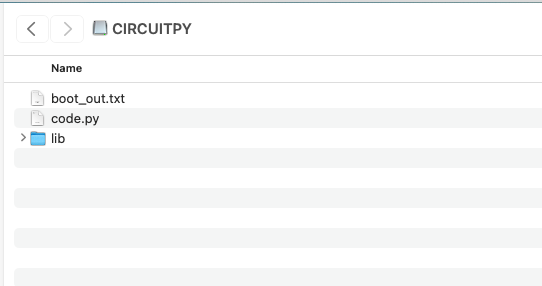
CIRCUITPY Folder
And blink.py needs to look like this:
|
|
- Confirm the code is compiling correctly and there aren’t any errors. To do this, you will need to view the board responses in your serial monitor program. An error will look like this:
Auto-reload is on. Simply save files over USB to run them or enter REPL to disable.
code.py output:
Traceback (most recent call last):
  File "code.py", line 7, in <module>
AttributeError: 'module' object has no attribute 'LED_'

Code done running.

Press any key to enter the REPL. Use CTRL-D to reload.
Note the “G” is missing from the end of “LED_” causing an error. I added “G” to the end and the board began to blink again. 5. If your board is not a SERPENTE or FIDI, have you installed the correct version of CIRCUITPYTHON? You may confirm what is running on the board by opening boot_out.txt, for the FIDI it reports:
Adafruit CircuitPython 8.0.0 on 2023-02-06; Serpente with samd21e18
Board ID:serpente
Step 2: Developing Code#
One of the more significant development issues with CircuitPython is all of the main programs have the same name, code.py. This is because CP looks for a file called code.py to begin execution. Which means there will need to be a file which will hold the code called something else, so you can store additional programs performing different tasks, which at sometime will be called code.py. A solution is to setup a process of tracking the different programs you develop for the board. I’ve found that I have three folders, examples, lib and utilities. I’ll discuss the second two folders later, lets focus on examples.
Create a base level folder, in my case, I called it FIDI, and in FIDI, I created examples, lib and utilities folders. I opened the folder examples, and opened code.py on the microcontroller, selected all of the code in code.py and copy/pasted it into a file called blink.py in examples. I also drag code.py from CIRCUITPY into the base level folder, FIDI. Now I have the beginning of my code development!
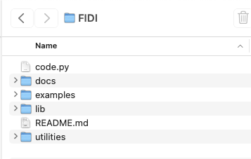
FIDI Folder
This framework allows for storing specifically named programs (scripts) in examples, and copy and pasting the file content into code.py when you wish to run the specific program.
I also added a folder called docs and it will contain pinouts of the FIDI board, the SAM21 datasheet and other necessary documentation.
Step 3: Adding Library Code#
Pretty quickly, or when you want to add some additional hardware or more than basic Python commands, you will need to add Library files. Or in my case, I wanted to use code which I developed into something which was always available. Not unlike library code in C or any other language.
For this to work well, you need to do two things, 1) all code which will be imported by your code.py program and is not already in the base CircuitPython code, will need to reside in the lib folder and 2) preferable as a pre-compiled mpy file, not as a text py file. The mpy format will result in a smaller file, which loads faster and runs faster than a py file. Performing the former action, is simple, store the desired file in the lib folder.
The second action, converting the file to mpy, will take using the mpy cross-compiler. Download the version from the page referenced and copy it into a folder on your execute path or in my case, I reference it absolutely like this /Users/lkoepsel/bin/mpy.py (more on this later.)
Here’s an example of how I use and create library files. The FIDI board has a RGB LED, I wanted to test how each of the combined colors worked so I created a simple routine which would light one, two or all three leds based on a letter of “r”, “g” or “b”:
import board
from digitalio import DigitalInOut, Direction


RED = DigitalInOut(board.LED_R)
RED.direction = Direction.OUTPUT
RED.value = True
GREEN = DigitalInOut(board.LED_G)
GREEN.direction = Direction.OUTPUT
GREEN.value = True
BLUE = DigitalInOut(board.LED_B)
BLUE.direction = Direction.OUTPUT
BLUE.value = True


def rgb(colors):
    if len(colors) <= 3:
        if 'r' in colors:
            RED.value = False
        else:
            RED.value = True
        if 'g' in colors:
            GREEN.value = False
        else:
            GREEN.value = True
        if 'b' in colors:
            BLUE.value = False
        else:
            BLUE.value = True
I copy the above test into a file called RGB_led.py and save it to lib. I then run the following:
mpy lib/RGB_led.py
cp -X lib/RGB_led.mpy CIRCUITPY/RGB_led.mpy
These two commands will 1) create a pre-compiled version of RGB_led.py called RGB_led.mpy and 2) will copy the file from the FIDI/lib folder on my computer to lib folder on the FIDI board.
And to use the code in my code.py file, I do the following:
# rgb_input - use to demonstrate rgb function
# enter r|g|b at terminal and appropriate led will light
import board
from RGB_led import rgb


while True:
    command = input()

    if command is not None:
        rgb(command)
By the way, this file is called rgb_input.py and it is saved in my examples folder. When I want to use it, I save any changes to my current code.py file into its appropriate file in examples and copy/paste all of rgb_input.py into code.py. Which I then load on to the board.
Step 3: Automate the Process#
My editor is always Sublime Text 4 (ST4) as I’m not fond of IDE’s and I’ve used Sublime Text (2->3->4) for many years. Within ST4, there is a build process, where you setup the commands to build the code for the processor. Automation is important for two reasons, first, it ensures you are always executing the same exact command, minimizing errors and second, it increases the speed of the build process. Here are the two build commands I use within ST4:
{
    "cancel": {"kill": true},
    "shell": true,
    "shell_cmd": "cp -fX code.py /Volumes/CIRCUITPY/",
    "variants": [
      {
          "name": "library",
          "shell_cmd": "/Users/lkoepsel/bin/mpl.sh $file "
      }
  ]
}
/Users/lkoepsel/bin/mpy "$1"
filename=$(basename -- "$1")
mpy_file="${filename%.*}".mpy
echo $mpy_file
cp -X "$mpy_file" /Volumes/CIRCUITPY/lib This is a JSON file which I save in /Users/lkoepsel/Library/Application Support/Sublime Text 3/Packages/User called CircuitPython.sublime-build. In ST4, I use Tools -> Build System -> CircuitPython to select this file. Then I use Shift-CMD-B to pullup either command. The copy command will copy the current code.py file onto the FIDI board and the mpl.sh command (shown above as a bash file), will run mpy.py on the file then copy the mpy version over to the FIDI board.
That’s it on the development process. While I was writing this, I discovered some shortcuts which can increase the execution speed of the CP programs on the board, I will write about those in an entry on execution speed on boards/languages.