Using the Labrador to examine the amplifier’s AC signal response.
Compared to the DC Sweep experiment, AC signal response is far easier to do.
Before we dive into how to perform the analysis, let’s discuss why we made the decision to add a bias resistor. Let’s start with the same amplifier design, however, we’ll use two supplies:
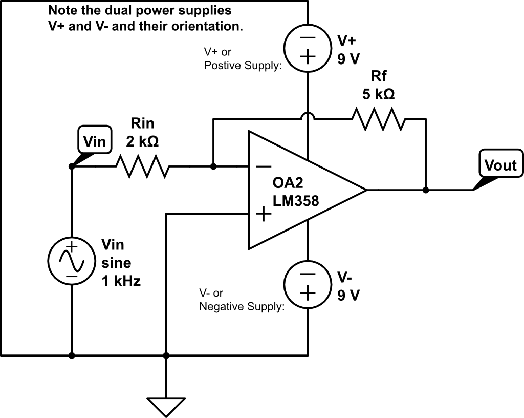
Inverting amplifier w/ dual supplies and no bias circuit
From the time domain graph, you can see a few things:
- Vo (Vout) is the inverse of Vi meaning its 180 degrees out of phase
- Vo is 2.5 greater than Vi so the gain is 2.5
- It is centered around 0V, and if we were to use only 1 supply we would lose the negative part of the signal.
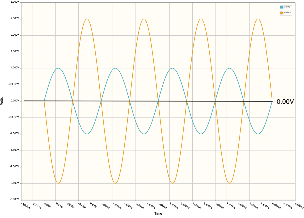
Inverting amplifier w/ dual supplies and no bias time domain graph
So we add a bias voltage to move the signal up. In this circuit, we moved it to the middle of 9V or 4.5V. On our breadboard we’ll use the Labrador power supply default which defaults to 4.8V:
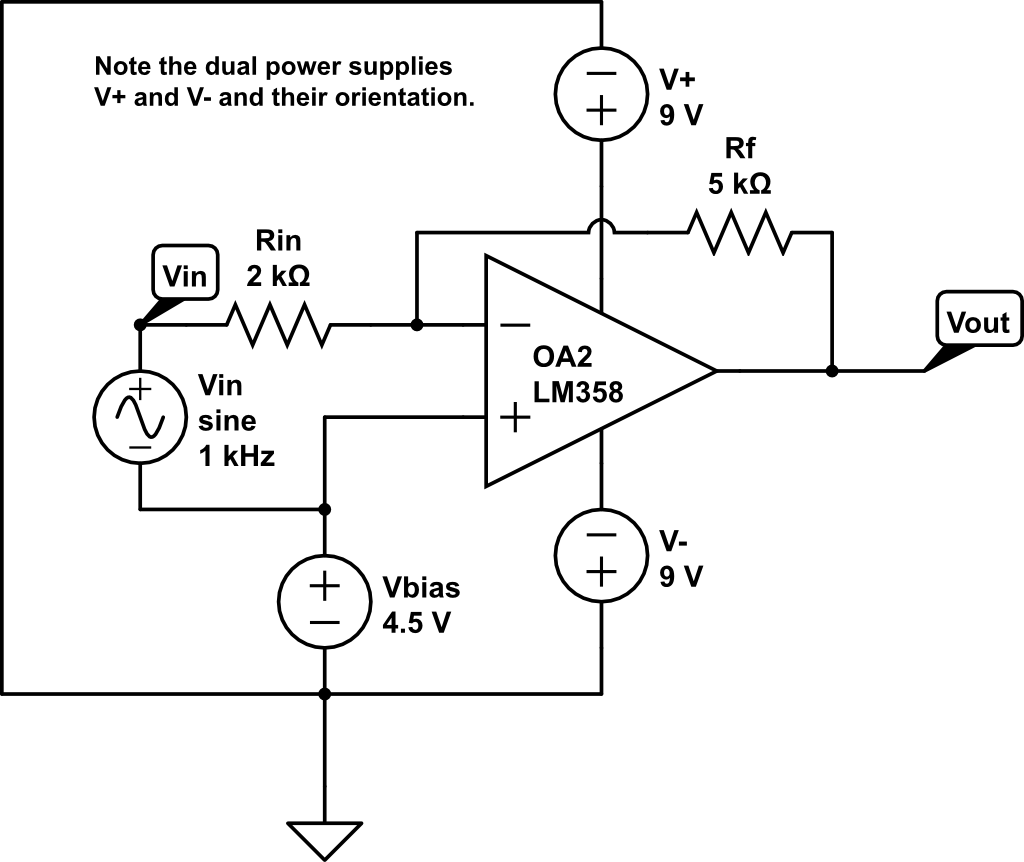
Inverting amplifier w/ dual supplies and 4.5V bias circuit
Here you can see a few things:
- same - Vo (Vout) is the inverse of Vi meaning its 180 degrees out of phase
- same - Vo is 2.5 greater than Vi so the gain is 2.5
- It is centered around 4.5V, which means we won’t lose the negative part of the signal.
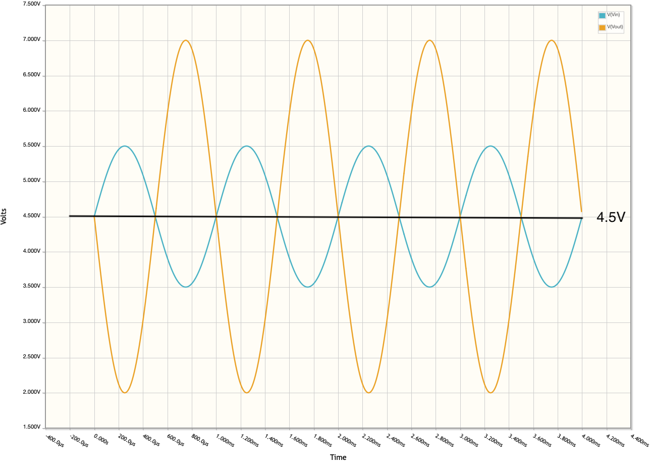
Inverting amplifier w/ dual supplies and 4.5V bias time domain graph
So we remove the extra supply (see circuit) and we re-run the time domain analysis and we have what we want to test:
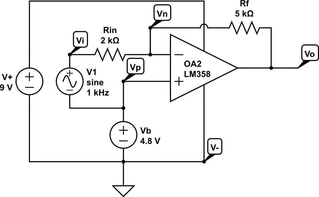
Inverting amplifier w/ single supply and 4.8V bias circuit
Let’s confirm our breadboard circuit performs as the following:
- Vo (Vout) is the inverse of Vi meaning its 180 degrees out of phase
- Vo is 2.5 greater than Vi so the gain is 2.5
- It is centered 4.8V (4.8V is the default rail voltage of the Labrador), which means we won’t lose the negative part of the signal.
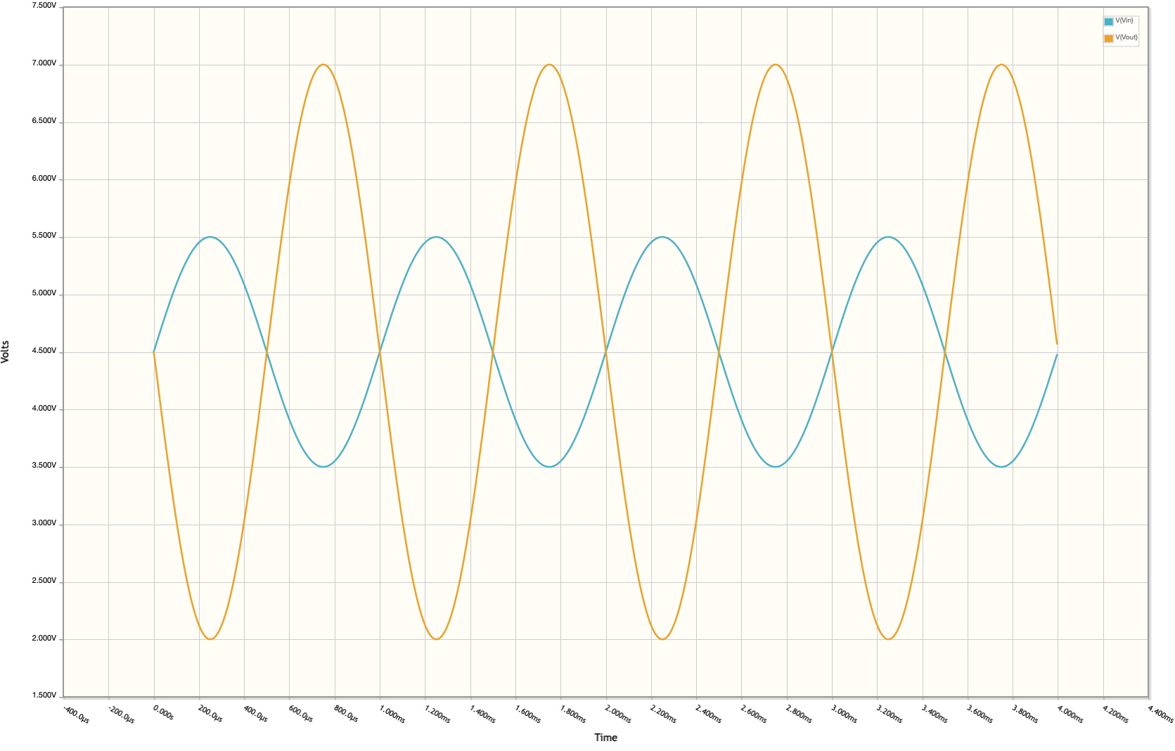
Inverting amplifier w/ single supply and 4.8V bias time domain graph
Note:#
There is an idiosyncrasy with the Labrador as to the signal generator (or my ability to understand it) that creates an “automatic bias” in the signal relative to the measurement. In other words, if I model the circuit as it is on the breadboard, the output voltage would be in saturation (even at the 500mV setting), however, if I model the circuit as shown in the schematic, it appears identical to the Labrador’s display. I explore this in greater detail here
After all that, it is relatively simple to perform the test.
- Use the same breadboard circuit as before.
- Disconnect the wire from Vv to Vi (the potentiometer to the input resistor)
- Connect a yellow wire from the Signal Generator CH1 (AC) to Vi
- Connect the Oscilloscope CH1 (DC) orange wire to the same row as #3 (Vi)
- Connect the Oscilloscope CH2 (DC) blue wire to pin 1 on the chip (Vo)
- Start the Labrador application
- Make sure both Oscilloscope 1 and 2 boxes are checked
- Press M to have the Range Dialog show on the screen and set Vmax to 7V
- Go to the Signal Generator CH1 box and ensure the following values are shown:
- Waveform: Sin (Sinewave)
- Frequency: 1kHz
- Amplitude: 1000mV (1V)
- Offset: 500mV
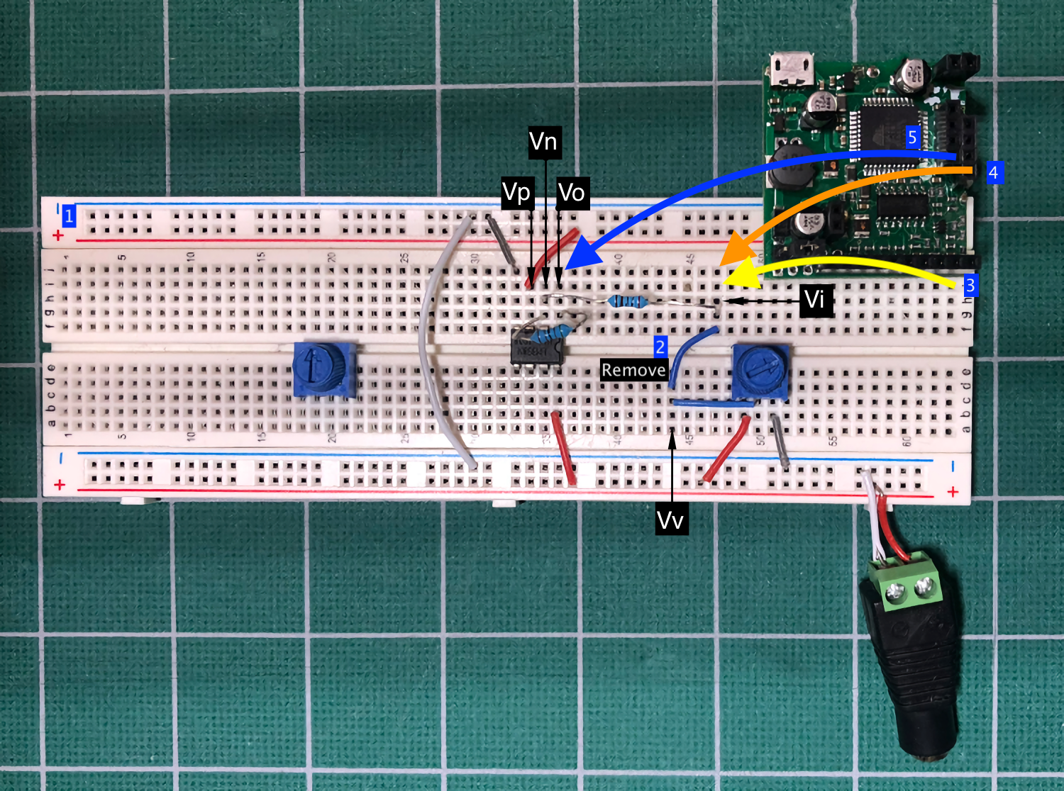
Inverting amplifier with bias breadboad
If all goes well, you will see a signal very similar to this:
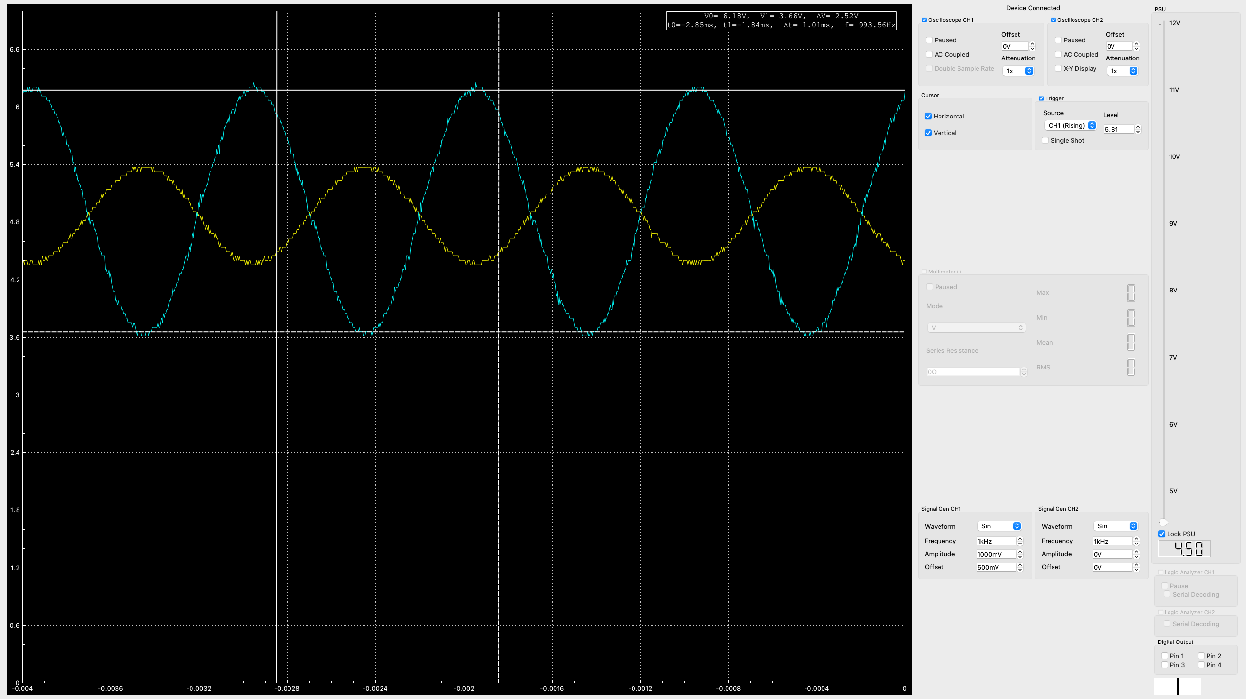
Labrador Application showing Time Domain graph
- Vo (Vout) is the inverse of Vi meaning its 180 degrees out of phase Confirmed
- Vo is 2.5 greater than Vi so the gain is 2.5 Confirmed
- It is centered 4.8V, which means we won’t lose the negative part of the signal. Confirmed
This wasn’t a difficult experiment, however, it lays the foundation for our next experiment where we add programmable bias and gain then use our amplifier to boost an externa signal.