If you followed the last couple of experiments, AC Signal Analysis and DC Sweep, you know you have a functional amplifier that will take either a DC level or AC signal and amplify it -2.5x. How do you know this? You were able to test the amplifier using the Labrador’s built-in Signal Generator.
This is nice, if that is the only signal you want to amplify. However, that isn’t the point of electronics! We want to explore and use our amplifier to amplify unknown signals! We want to put it to use!
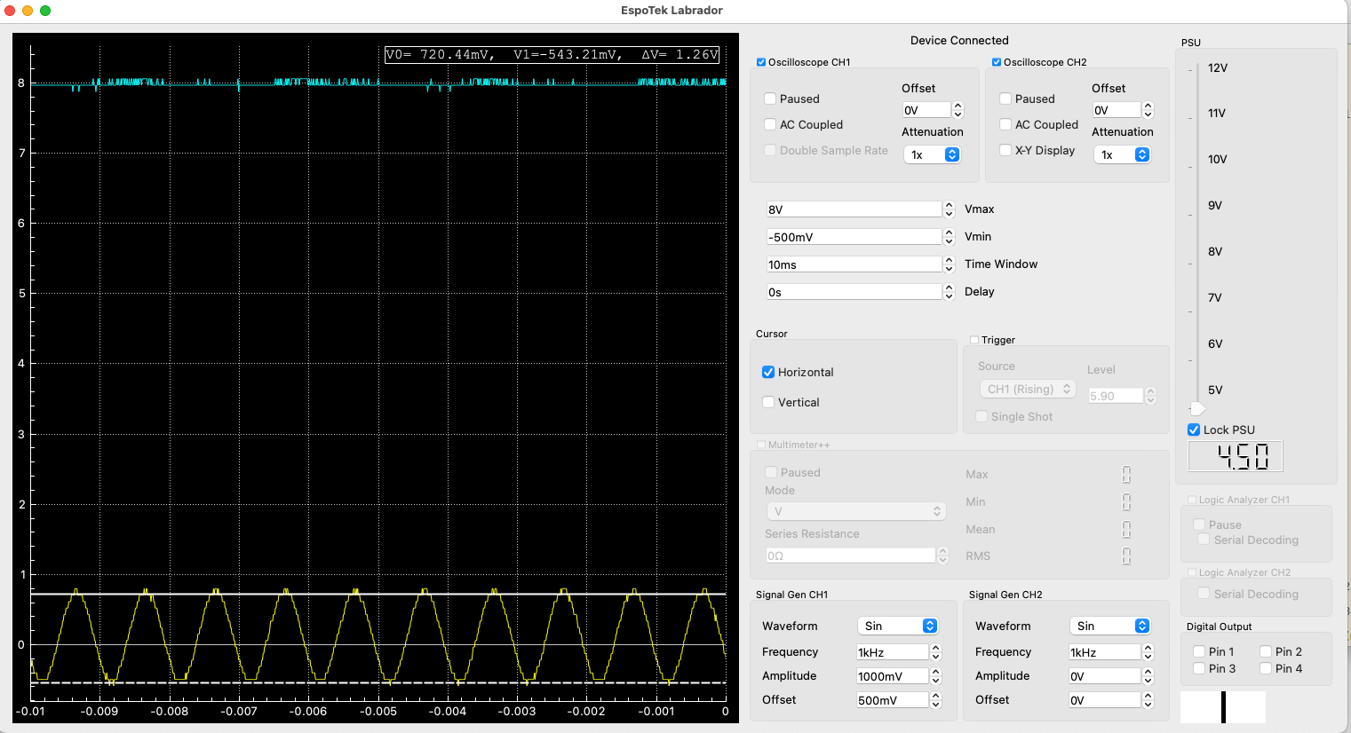
So we grab a handy tablet, we use the browser to go to a Online Tone Generator and we dial up another 1Khz signal. We still have our orange wire going to Vi and our blue wire going to Vo and we can see Vi. We had to increase the volume on the website and on our tablet, however we’ve got roughly a 1.2V sinusoidal signal. We can see it in the Labrador application, however CH2 is doesn’t look right!
We know from our previous analysis that our amplifier operates in a range of 3.5V to 6.5V, and this signal ranges from -.6V to +.6V.
We also know our amplifier requires a bias voltage to avoid going into saturation.
So due to points 1 & 2, we’re seeing a good example of what happens when our amplifer isn’t operating in its operational range. It goes into saturation, otherwise known as a flat line.
Let’s fix that by doing the following:
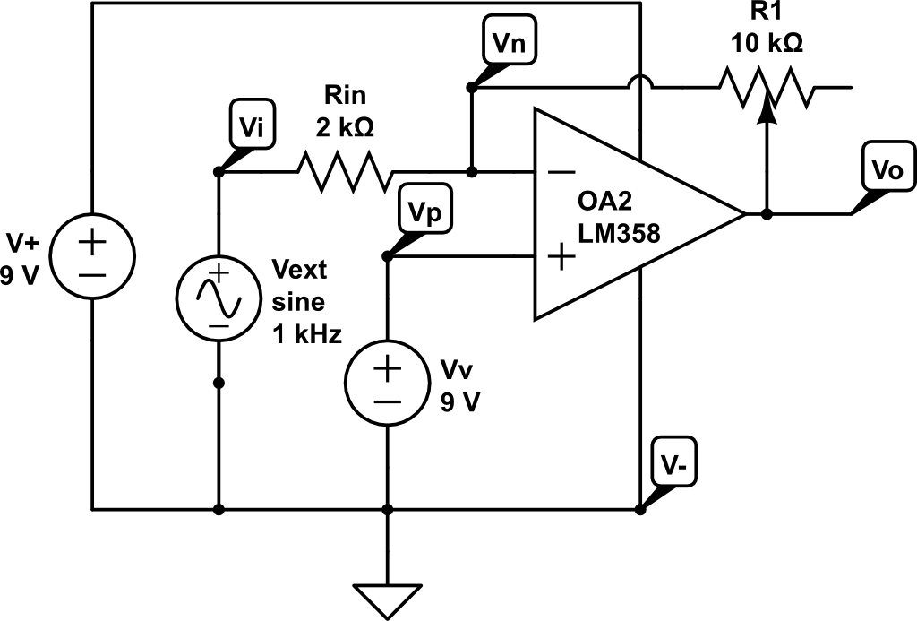
Remove both Rf, the resistor between pin 1 and 2 and Vbias, the wire from Labrador positive rail to pin 3
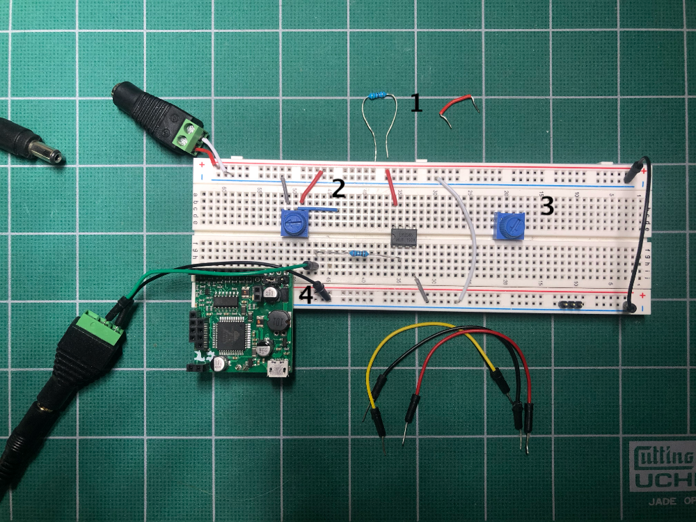
Connect a wire between Vv, the pot on the left to pin 3 for a variable Vb. (Wire not shown, use one of the connecting wires shown below the breadboard.)
Connect a wire from the left terminal on the right pot to pin 1 and the center terminal to pin 2. The right terminal remains unconnected. (Wire not shown, use one of the connecting wires shown below the breadboard.)
Add an external signal source, Vext. In our case we used an audio barrel connector with one of the two signal pins as our source and the ground pin to breadboard gnd.
New circuit with programmable bias and gain
Breadboard for making changes
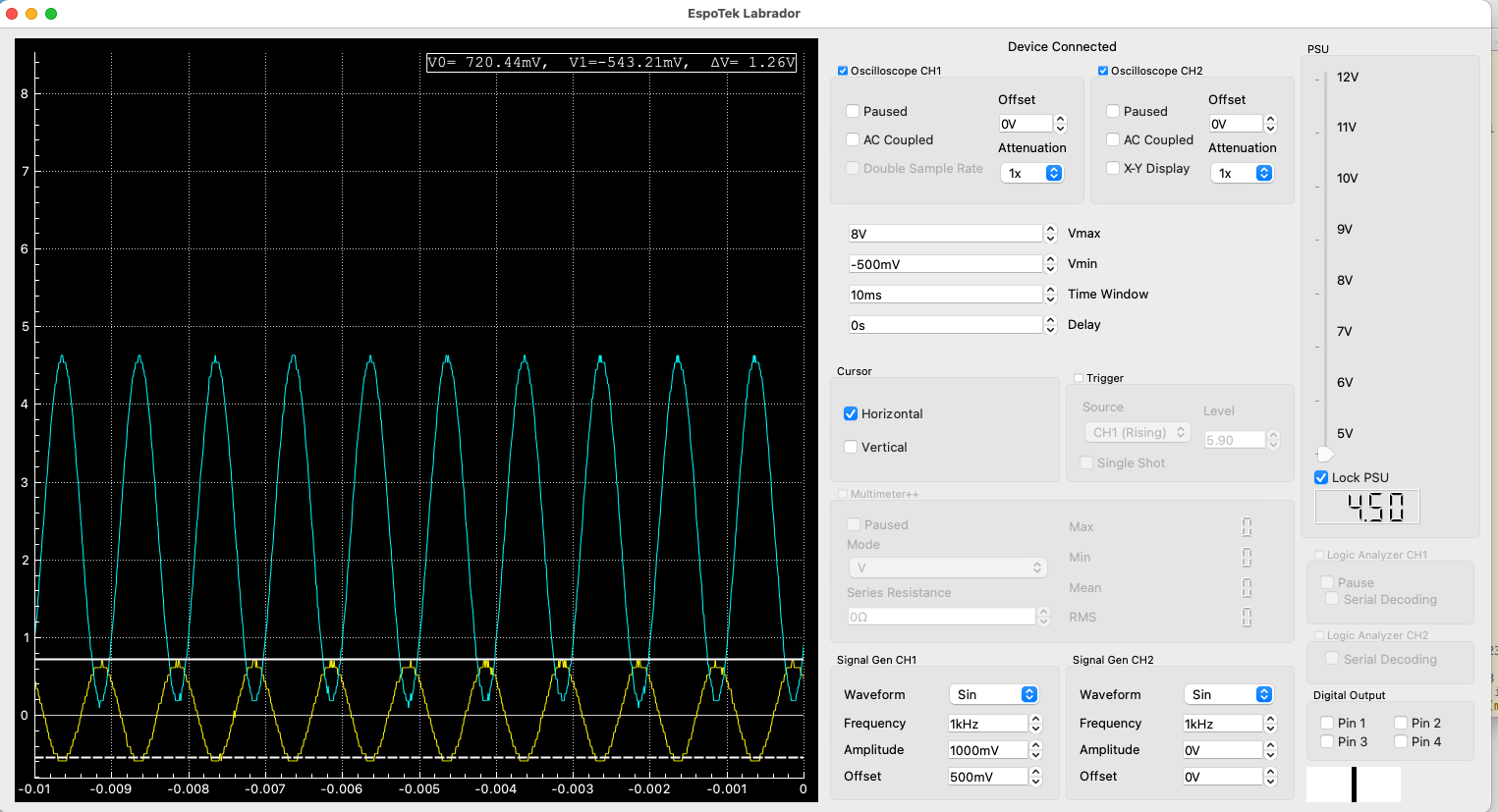
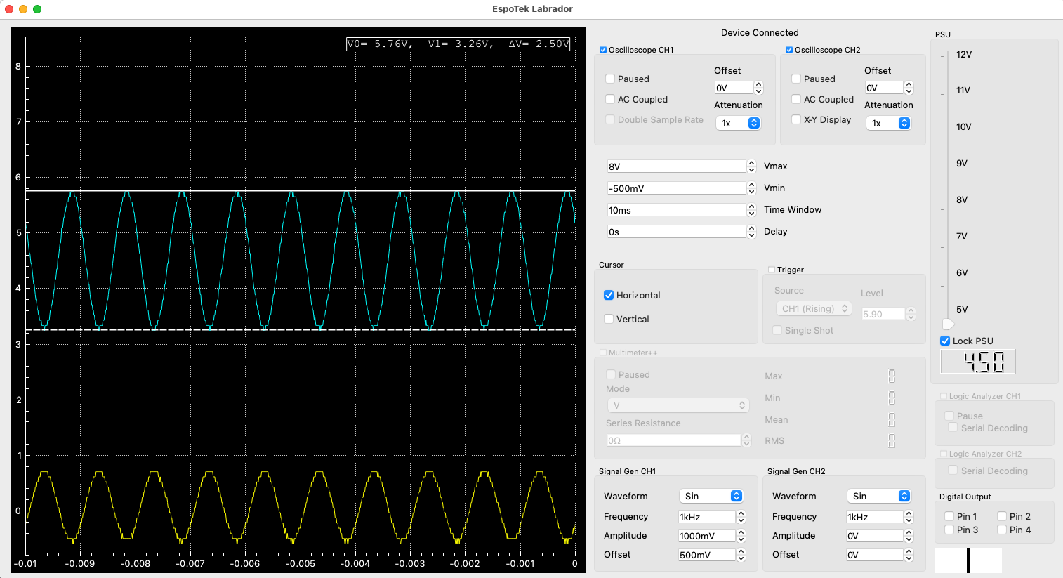
These changes allow us to “dial-in” both our feedback resistance and our bias voltage. When they are adjusted properly, we can see the signal very easily on our Labrador application. For example, if I set the two pots to approximate our original Vb of 4.8V and Rf of 5K ohms, I will get an nearly identical Vo to what I had with the fixed values. Once I begin to adjust the bias, I can immediately begin to see a signal and I can also adjust the amplification (Rf/Ri) as well!
External 1Khz signal with bias and gain adjusted to show Vo
External 1Khz signal with bias and gain adjusted to show original Vo (-2.5xVi)
Now I have an amplifier that will operate in a far broader range than what we originally designed. If I carefully adjust the bias such that the base of the Vo signal is about 2V, I’m able to maximize the gain at -5x! And I have a very clean output signal.
External 1Khz signal with bias and gain adjusted to show maximum Vo (-5xVi)
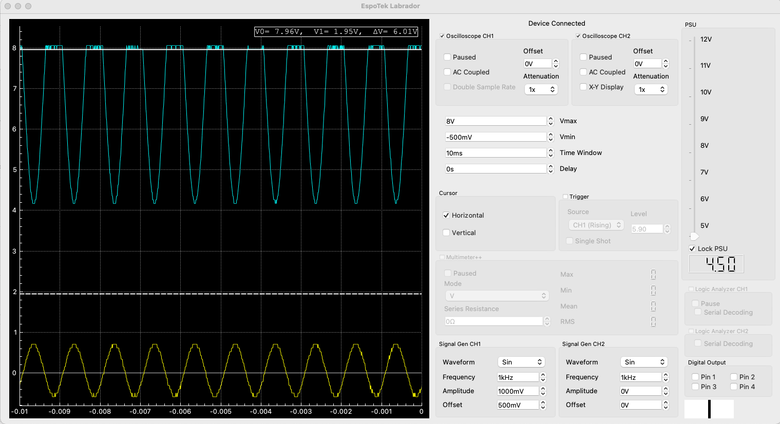
On the other hand, if I don’t adjust the bias properly, I begin to see saturation of the amplifier as the signal Vo begins clip above 8V.
External 1Khz signal with bias and gain adjusted to show clipping of Vo