Where I describe how to use the servos() interface in AVR C.
Sources#
- Analog Feedback Micro Servo - Product ID: 1449 Servo to be used in entry.
- Analog Feedback Servos
- Arduino Lesson 14. Servo Motors
- Adafruit Servo Motors
Introduction#
Servos are a powerful addition to the embedded programming toolkit as they enable motion. Not high-speed motion as in a electric motor, however, motion which can be easily controlled and typically in an arc or as angles. Servos are much more precise as to how they can move in comparison to electric motors. See Sources above for a few example tutorials as to how to use them.
In this entry, I’m going to demonstrate how to setup a timer to specifically drive two servos as well as demonstrate how to control up to 6 servos using the ATmega328P. This entry is designed to demonstrate how to write code to control servos, as compared to “how to write code to call servo functions”.
Servo Control#
A servo is controlled by an signal pulse. There are two criteria for the pulse to be effective and cause the servo to move, a) the pulse must be in a specific frequency range and b) the width of the pulse, which serves to control where it moves, must be in a specific range as well. The best advice I’ve seen as to the frequency is from Elliot Williams:
“Control Pulse Frequency The pulse rate of one control pulse per 20 ms is fairly flexible. My servo works anywhere from 10 ms to about 25 ms. Delays shorter than 10ms seem to mess up the deadband circuitry, and because the motor only engages for a maximum of 25 ms per pulse, longer PWM periods allow the motor to disengage a tiny bit before it turns back on, but you might not even notice this in practice. In short, the inter-pulse timing isn’t critical.” Excerpt From Make: AVR Programming Elliot Williams
In my testing, it is relatively easy to create a 61kHz signal from Timer/Counter 0, and I found I was able to control my Adafruit Analog Feedback Micro Servo using this signal.
The second part is the width of the servo pulse, again, its best to listen to experts and Adafruit advised:
Note that the default servo pulse widths (usually 1ms to 2ms) may not give you a full 180 degrees of motion. In that case, check if you can set your servo controller to custom pulse lengths and try 0.75ms to 2.25ms. You can try shorter/longer pulses but be aware that if you go too far you could break your servo!
In my testing using the above servo, I needed a 500us (.5ms) pulse to move to 0 and a 2.3ms pulse to move to 180. In reality, I believe my servo was moving from 0 degrees to about 160 degrees.
The nice thing about the servo referenced, is that it includes a feedback line which allows you to read where the servo is positioned. While servos are intended to be “precise mechanical steppers”, given it’s $9.95 cost, this servo is not precise nor even accurate at times. It helps to have feedback to know specifically where the servo has moved.
Ultimately, you will want to see a waveform which looks like this:
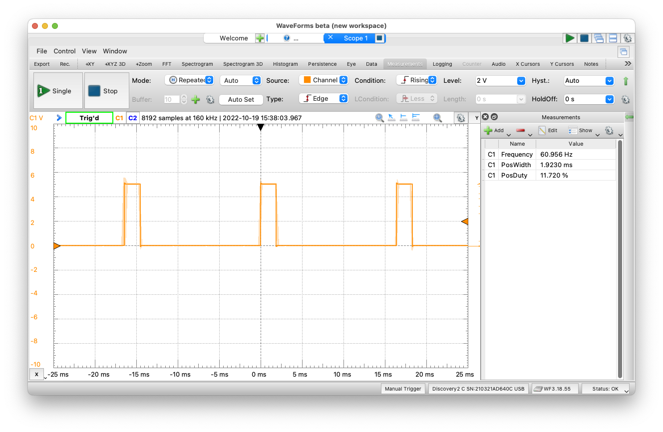
Waveform of servo signal
In the image above, the signal is 60.96kHz with a 1.922ms positive pulse width. Another way to think about the signal is it is a 60.96kHz waveform with a 11.7% duty cycle. See Developing in C for the ATmega328P: Function - analogWrite() for understanding PWM and the duty cycle of signals in greater detail.
This specific width and frequency drives the servo to approximate position 425.
Circuit#
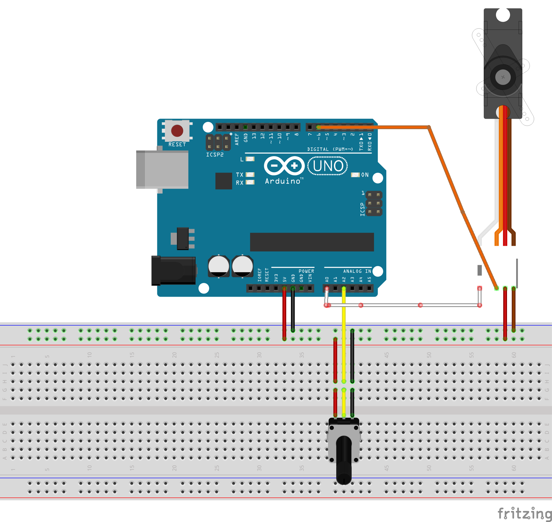
Here is the circuit for the software:
- The servo has four leads, power(red), ground(brown), control(orange) to pin 6 and feedback(white) to A0
- The pot has three leads, right(power), left(ground) and center to A2
- The Uno power(5V) and ground(GND) are connected to power and ground rails on the breadboard
Waveform of servo signal
Servo Coding#
I’ll walk through the entire servo_0 example, showing the specific line numbers from the file.
Step 1 Setup Timer 0#
The first step is to setup Timer 0 and ensure you can get a proper frequency (between 10ms and 25s periods or 40Hz to 100Hz frequency). I looked at the code for setting up Timer 0 for the millis() clock then adjusted from there. Its a simple setup, however, I went for Fast PWM on Timer 0. Once I set it up and the 61kHz signal appeared, I was finished. (For more information as to how to do this in Linux, using bloom and gdb, see this entry.
|
|
The next step is to ensure I can control the width of the pulse, which will determine where the servo will move. The easiest method to do this is to simply view the pulse on the scope (Waveforms) and determine which values will give me a range of .5ms to 2.3ms.
Another method to determine if your signal is correct is to use a digital multimeter with a frequency measurement and duty cycle capability. If so, follow these steps:
- Measure the frequency, it needs to be in the range 40Hz to 100Hz.
- To obtain the period of the frequency use 1/frequency * 1000 to get the period in milliseconds.
- Press your DMM mode button to obtain the duty cycle, it will probably be in the range of 2-5%, multiply it times your period in step 2 and this will be the pulse width. The pulse width needs to be between .5ms and 2.3ms.
The variable I need to affect this change is either OCR0A (for pin 6) or OCR0B (for pin 5). For additional details as to how I knew this, see this entry.
I wrote a function which would check the value to ensure it is in the proper range, then it would set OCR0A. I also check the position of the servo by reading an analog port connected to the white wire from the servo. The function returns with this value, after I have delayed sufficiently to allow the servo to move to the position based on the pulse width.
|
|
Control Code#
The main function initializes then controls the servo. The servo position is controlled by a value from the potentiometer. As the potentiometer is turned from right to left, the servo moves from 0 degrees to 180 degrees. The values from the pot are 10-bits ranging from 0-1023 and are mapped to values appropriate to the servo from 6 (minimum pulse width of .5ms) to 36 (maximum pulse width of 2.3ms). The delay(1) served as a way for me to have a nop in my code for a breakpoint.
|
|
Debugging with avr-gdb#
Programming Gotcha#
While I was debugging the program using avr-gdb, I ran across some optimization issues. From time to time, the gcc compiler would optimize out one of my variables which were required for controlling the timer. Maddeningly, it wouldn’t be consistent, I would simply see a message as to a variable <optimized out> and the program wouldn’t work.
Using a breakpoint#
There is a delay(1); in the code at line 121, this line was used to allow me to catch a breakpoint after the servo had moved and check the values for the servo position (servo_pos), the pulse width (servo_pulse) and the control pot (control_pos) value. Using these values, I could determine if the program was working properly. My process (in Linux) would be to start bloom as my gdb server, then avr-gdb as my debugger. I would set the breakpoint at 121, display my 3 variables and let the debugger (c)ontinue. It would move the servo then stop and display the values, and example of several iterations of this is below:
(gdb) br 121
Breakpoint 1 at 0x1a8: file main.c, line 121.
Note: automatically using hardware breakpoints for read-only addresses.
(gdb) disp control_pos
1: control_pos = 1023
(gdb) disp servo_pulse
2: servo_pulse = 36 '$'
(gdb) disp servo_pos
3: servo_pos = 499
(gdb) c
Continuing.

Breakpoint 1, main () at main.c:121
121         delay(1);
1: control_pos = 1023
2: servo_pulse = 36 '$'
3: servo_pos = 499
(gdb) c
Continuing.

Breakpoint 1, main () at main.c:121
121         delay(1);
1: control_pos = 0
2: servo_pulse = 6 '\006'
3: servo_pos = 127
(gdb) c
Continuing.

Breakpoint 1, main () at main.c:121
121         delay(1);
1: control_pos = 437
2: servo_pulse = 18 '\022'
3: servo_pos = 273
(gdb)
Complete Program#
|
|
Controlling Upto 6 Servos#
This version of the servo control code will control up to 5 servos on any of the digital pins. The control outcome is the same as above, an approximately 50Hz signal with a positive pulse width of .5ms to 2.3ms. To deliver this waveform, one must adjust the following parameters:
- servo.h:MAX_SERVOS - set the total number of servos between 2-6
- servo.c:SERVO_PULSE_WIDTH - count required for a frequency of ~52Hz
- servo.c:set_servo:high_count - count required for desired pulse of .5ms to 2.3ms.
Constants are defined in servo.h with required values. The constants are shown below, 5 servos are being configured:
// Uncomment block of defines based on number of servos
// Parameters create a 52.1Hz frequency with pulse range .5ms to 2.3ms

// Using 2 servos
// #define MAX_SERVOS 2
// #define SERVO_PULSE_WIDTH 600
// #define HIGH_COUNT_MAX 72
// #define HIGH_COUNT_MIN 16

// Using 3 servos
// #define MAX_SERVOS 3
// #define SERVO_PULSE_WIDTH 400
// #define HIGH_COUNT_MAX 50
// #define HIGH_COUNT_MIN 12

// Using 4 servos
// #define MAX_SERVOS 4
// #define SERVO_PULSE_WIDTH 300
// #define HIGH_COUNT_MAX 36
// #define HIGH_COUNT_MIN 8

// Using 5 servos
#define MAX_SERVOS 5
#define SERVO_PULSE_WIDTH 240
#define HIGH_COUNT_MAX 29
#define HIGH_COUNT_MIN 6

// Using 6 servos
// #define MAX_SERVOS 6
// #define SERVO_PULSE_WIDTH 200
// #define HIGH_COUNT_MAX 24
// #define HIGH_COUNT_MIN 5
The process is ensure MAX_SERVOS and SERVO_PULSE_WIDTH are set appropriately then use set_servo() to set high_count for desired pulse width or position of servo. Subsequent calls to set_servo() will move servo to new position based on pulse width. To determine position of servo, it will be important to setup a function which polls the feedback wire and translates the value to a position. This is demonstrated in the first servo code on this page.
Required for examples/multi_servo
- In Makefile, on CPPFLAG line add: -DSERVO=$(SERVO)
- In env.make add (when not using servo code, change to 0): SERVO = 1
- Setup the hardware servo using wiring similar to the Circuit above
- Compile-link-load examples/multi_servo
- Open a serial terminal program (i.e, CoolTerm) and follow the prompts:
Enter servo and angle: EX:2 120 Servo 0 to angle   0    Pulse width: 15 Servo Pos: 108
Enter servo and angle: EX:2 120 Servo 0 to angle 180    Pulse width: 72 Servo Pos: 491
Enter servo and angle: EX:2 120 Servo 0 to angle   0    Pulse width: 15 Servo Pos: 108
Enter servo and angle: EX:2 120 Servo 0 to angle  90    Pulse width: 43 Servo Pos: 307
Enter servo and angle: EX:2 120 Servo 0 to angle  45    Pulse width: 29 Servo Pos: 211
Enter servo and angle: EX:2 120 Servo 0 to angle 112    Pulse width: 50 Servo Pos: 353
This code uses Timer/Counter 0 which conflicts with using tone().