Where I evaluate an interesting prototyping board using CircuitPython.
Sources#
Introduction#
I ran across this board, the omzlo FIDI via an Adafruit blog article. I was struck by its size and utility along with its relative powerful processor for its size. From the webpage:
- Microchip ATSAMD21E18A 32-bit Arm Cortex M0+ running at 48MHz, with 256KB flash, and 32KB RAM
- 4MB flash for CircuitPython code and other files
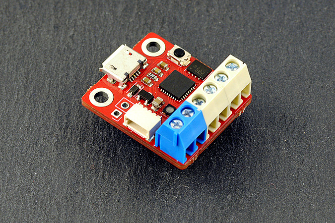
omzlo FIDI
Their recommendation was to use CircuitPython (CP) to program as CP is a fast, prototyping language and this board with its terminal block and qwic connectors, is a board designed for prototyping. While most of my work lately, has been in C, I’ve used Python quite a bit in utility programming for my computer. I thought it might be worthwhile to try the board and CP out.
As omzlo is based in Greece, the boards took about a month to show up. Not ideal, however, patience can be a virtue. :) In this case, the wait was well worth it. I love the form factor and outside of the overhead of learning CP vs MicroPython vs Python vs C, I really enjoyed this project!
The Project#
A couple of months ago, I created an ultrasonic rat repeller using an Uno, a couple of buttons and a ultrasonic transducer (speaker). I wrote the project in AVR_C and based it on a simple four state finite state machine. It worked well! It seemed to drive the rats out of my wall and it was easy to use in the middle of the night. (Which apparently is when rats want to make lots of noise.)
I thought I would develop the same project using the FIDI, CircuitPython and a simple prototyping board.
My finished version (without packaging) looks like this:
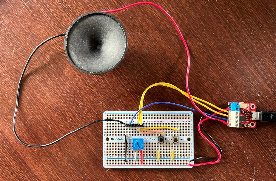
Ultrasonic Repeller
The two button drive the state machine, one for cycling UP through each state and the second is an ENTER button to “enter and execute the state”. For my purposes, I wanted to have three states for audio, audible, ultrasonic low and ultrasonic high. The fourth state, the initial state 0, was a null state where no sound was being transmitted. The board would boot into this state.
On the Uno version, I added two additional leds, the two of them would indicate the state in binary. The FIDI has an RGB led, and I haven’t determined a good indication of state using the colors red, green and blue.
The Software#
Most finite state machine examples written in Python take an object-oriented approach. I’m not a big fan of object-oriented code. For two very good reasons, one, I believe its a significant overhead for embedded microcontrollers and two, I don’t understand it. Its probably the latter, which drives me to avoid it, however, I’ve seen multiple conversations where software developers for embedded projects also criticize object-oriented code for not only its overhead, the abstraction offered isn’t of value on a resource-limited device.
This said, I did find using namedtuple instances as a lightweight version of encapsulation of great value. Buttons are connected to D0 and D1, and a press of DO, moves UP through the states, while a press of D1, ENTERS the state. I did the following, I identified the attributes I required to describe a state instance:
- What is the next state based on the button pressed?
- What color is the led indicator?
- What function do we run?
Or from the code documentation:
state: current state
on_D0: state to move to based on press of button on D0
on_D1: state to move to based on press of button on D1
led_D0: led color based on rgb() to light based on D0
led_D1: led color based on rgb() to light based on D1
func_D0: function to execute based on D0
func_D1: function to execute based on D1
Example:
state_1 = states(1, 2, 1, 'g', 'rb', audible_off, audible_1)
You can see from the Example above, we can easily characterize a state instance using a namedtuple instance.
The code to cycle through each state looks like this:
while True:
    # check button, if pressed respond appropriately
    pressed = buttons()

    if (pressed is not None):
        change = True
        while (change and state == 0):
            change = False
            state = states(state_0)

        while (change and state == 1):
            change = False
            state = states(state_1)

        while (change and state == 2):
            change = False
            state = states(state_2)

        while (change and state == 3):
            change = False
state = states(state_3)And the STATES code executes via the namedtuple instance:
def states(STATE):
    if pressed == "D0":
        state = STATE.on_D0
        rgb(STATE.led_D0)
        STATE.func_D0()
        print(f"state {STATE.state} UP {state=}")

    elif pressed == "D1":
        state = STATE.on_D1
        rgb(STATE.led_D1)
        STATE.func_D1()
        print(f"state {STATE.state} ENTER {state=}")

    else:
        rgb('r')

return(state)I believe the software is simple enough to be able to make changes such as adding new states or reconfiguring what happens in each state without a lot of work. The code which isn’t shown are the functions which happen based on the state (as in func_D0 or func_D1). Those functions can be anything one wants to happen as te user cycles through each state.
The repository is above in Sources, feel free to download and use yourself! If you want to know in greater detail, how to develop CircuitPython code for the FIDI (or similar boards), here is an entry.