Where I describe how to use Forth with an Arduino Uno and make it easier to program the Uno in Forth.
Introduction#
The Arduino Uno benefits from an incredible software framework. Between the programs already developed by the Arduino organization, and the hundreds of libraries which were created by others, you can find a program which does what you need. This makes it extremely easy to hit the ground running with a project. FlashForth isn’t like this.
FlashForth or even Forth in general doesn’t lend itself well to the programming library concepts embodied by C/C++/Arduino. Forth is designed to be written for a specific application, quickly, bug-free and relatively high performance. If you are reading this, I’m assuming you’ve already grasped and accepted this, both the advantages of using the Arduino software framework and the benefits of developing in Forth. If you want to explore more, this page has links which would help.
An Example#
I spent a fair amount of time reading the late Jeff Fox’s treatise on developing code in Forth. As I read it, I realized I was doing what he was criticizing, which was rewriting “C” code in Forth. He was right, Chuck Moore was right and they will continue to be right. Forth is different and you solve problems differently using Forth than you do in other languages.
The key development points I took away from “Thoughtful Programming and Forth” were:
- Forth is interactive.
- Forth is extensible.
- Use the stack.
C is not any of these three things. In embedded C, it is painful to be interactive, extending C is not easy and there isn’t the stack (or atleast easily accessed). However, I was writing Forth code as I would C code.
For example, I was testing a very simple timing test, to determine if the word ms was accurate. I wanted to toggle a pin at a specific interval than use an oscilloscope to view the waveform.
: time_10ms ( -- ) \ very accurate timing, can range down to 1ms/loop
	D3 output
	begin
		D3 toggle
		10 ms
	again
;
The above routine has the time embedded in the code. Why? Because that is how you have to do it in C! Once I replaced the 10 with dup, I was able to easily and quickly test the timing loop for any length of time. Further more, my loop was more efficient! (There is less overhead in using the stack than pulling a number from flash.)
I found myself in a similar predicament when I started developing code using the ATmega328 PWM capabilities. I attempted to “re-write” my C PWM code in Forth. Once again, it didn’t go well. Once I broke away from the C paradigm, and began to play in Forth, the PWM became much easier!
This is all to say, you are starting from scratch. And in starting from scratch, we’ll need to re-examine the Arduino Uno so we can use it.
Arduino Uno#
The pinout of the Arduino Uno, again:
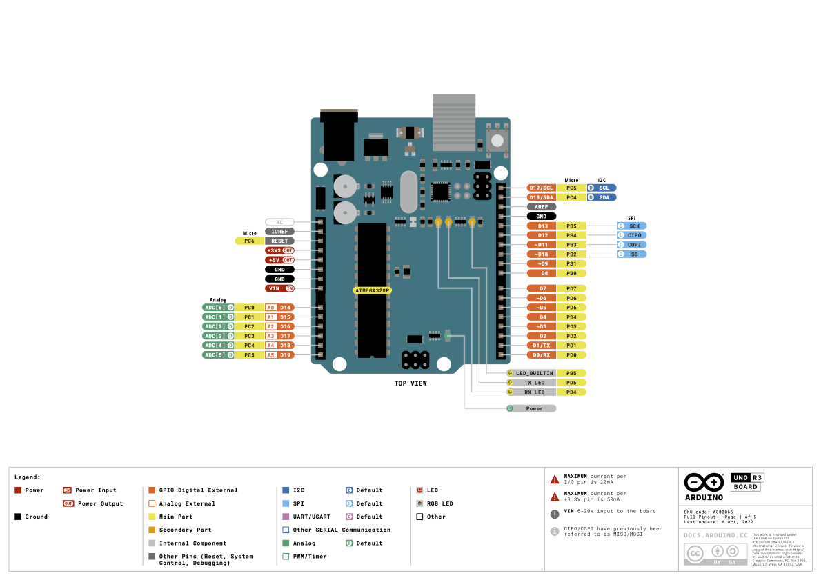
Arduino Uno R3 Pinout
On the right-side of the image, there is a tall column of pins. Starting with PC5 at the top, down to PD4 at the bottom In this entry, we’ll focus on developing words which facilitate working with these pins.
Port B and Port D#
If you look closely at the pin out image above, starting at the bottom corner of the board (above LED_BUILTIN), you will see PD0-PD7 and PB0-PB5. These are the pins associated with Port D and Port B, respectively. The number following the B or D, is the bit number.
For example, PB5, which we used for the on-board LED, is Port B, bit 5. Connecting to that pin (which is 5th pin from the top), will connect you to PB5. The value on the pin, will be the same value the LED shows. When the pin is high, the LED will light and when the pin is low, the LED will be off.
You can rightly assume that the lower 8 pins are associated with Port D, bits 0-7 and the next 6, are associated with Port B, 0-5. In the blink discussion, I introduced the concept of three registers for each port and we dealt with the registers for Port B. There are the same 3 registers for Port D, however, at different addresses. Therefore, to control those 14 pins, you need to use the 3 registers for Port B and the 3 registers for Port B.
One more thing, its best to ignore the first two pins at the bottom, PD0 and PD1. These are the serial port pins connected to the USB chip and messing with them will cause havoc with your serial port. Leave them alone, use pins PD2-PB5, or 12 pins.
ATmega328P Input/Output (I/O) Registers#
(for details see the ATmega328P datasheet, DS40002061B-page 100)
Technical data on the ATmega328P’s ports, each port on the ATmega328P has 3 registers:
- PORTn - the output value on the port, whether it is set high or low, address $25 for Port B and address $2B for Port D
- DDRn - the data direction register, sets the port to be an input or an output, address $24 for Port B and address $2A for Port D*
- PINn - the input register, is the value on the port as an input, address $23 for Port B and address $29 for Port D
As we did in blink, the rules of using the registers is quite simple:
-
PORTB/D: A “1” or “0” written to a bit in PortB/D, will put that pin at 5V or at GND, respectively, if the specific bit has been made an output (see DDRn).
-
DDRB/D: A “1” or “0” written to a bit in DDRB/D, will make that that pin an output or input, respectively.
-
PINB/D:
a. if the specific bit has been configured as an output (see DDRn) on PINB/D, writing “1” to the bit, will toggle the output value on that pin.
b. If the bit has been configured as an input, reading the bit in PINB/D, will be the input value on that pin.
Required Information#
It helps to have some information “baked” into Forth, regarding the Uno. Little things like bit patterns, port addresses will simplify how we construct our words. Let’s start with the following:
Ports and Bits#
\ Ports, DDRx, PORTx and PINx, page 624 datasheet
$23 constant PINB  \ Port B input register
$24 constant DDRB  \ Port B data direction register
$25 constant PORTB \ Port B output register
$29 constant PIND  \ Port D input register
$2a constant DDRD  \ Port D data direction register
$2b constant PORTD \ Port D output register

%10000000 constant BIT7   \ bit 07
%01000000 constant BIT6   \ bit 06
%00100000 constant BIT5   \ bit 05
%00010000 constant BIT4   \ bit 04
%00001000 constant BIT3   \ bit 03
%00000100 constant BIT2   \ bit 02
%00000010 constant BIT1   \ bit 01
%00000001 constant BIT0   \ bit 00
We know that the combination of bit and DDRB/D address made things easy in blink, let’s do that for all of the pins! Not only that, let’s move to Uno-based references as compared to ATmega328P:
Uno Pin References#
\ Arduino Board Pins, reference using Board Pins
\ not AVR registers if possible
\ Pins referenced by nn, where nn is the Arduino board pin number
BIT5 DDRB 2constant LED \ Board Connector 13 PB5
BIT5 DDRB 2constant D13 \ Board Connector 13 PB5
BIT4 DDRB 2constant D12 \ Board Connector 12 PB4
BIT3 DDRB 2constant D11 \ Board Connector 11 PB3 PWM OC2A
BIT2 DDRB 2constant D10 \ Board Connector 10 PB2 PWM OC1B
BIT1 DDRB 2constant D9  \ Board Connector  9 PB1 PWM OC1A
BIT0 DDRB 2constant D8  \ Board Connector  8 PB0
BIT7 DDRD 2constant D7  \ Board Connector  7 PD7
BIT6 DDRD 2constant D6  \ Board Connector  6 PD6 PWM OC0A
BIT5 DDRD 2constant D5  \ Board Connector  5 PD5 PWM OC0B
BIT4 DDRD 2constant D4  \ Board Connector  4 PD4
BIT3 DDRD 2constant D3  \ Board Connector  3 PD3 PWM OC2B
BIT2 DDRD 2constant D2  \ Board Connector  2 PD2
BIT1 DDRD 2constant D1  \ Board Connector  1 PD1
BIT0 DDRD 2constant D0  \ Board Connector  0 PD0
While this is appears like a lot of code, it helps to realize its bit-specific, which means there are 8 lines for PORT D and 6 for PORT B, hence a fair amount of duplication.
Rules to Words#
We need to convert the rules above for the ports into words. And once we do, this becomes much easier to understand. We know we want to be able to do the following things with an I/O pin, preceded by the word we would want to use:
out: Set as output - set bit in DDRB/Din: Set as input - clear bit in DDRB/Don: Write as high - set bit in PORTB/Doff: Write as low - clear bit in PORTB/Dread: Read value - read PINB/Dtog: Toggle value - set bit in PINB/D
Let’s look at our blink rules:
Pin Words#
: out ( bit port -- ) mset ;  \ set pin as output
: in ( bit port -- ) mclr ;  \ set pin as input
: on ( bit port -- ) 1 + mset ;  \ set a pin high
: off ( bit port -- ) 1 + mclr ;  \ set a pin low
: tog ( bit port -- ) 1 - mset ; \ toggle the pin
These continue to look to serve the same value. For example, enter empty then copy and paste the sections Ports and Bits, Uno Pin References and Pin Words into CoolTerm. Be sure every line has an “ok” at the end of it.
Then try:
D13 on
D13 off
Did the LED turn on and off?