Where I use the Labrador to test specific functions of the ESP32 running MicroPython.
Sources#
- Quick reference for the ESP32
- ESP32-GetStarted
- Adafruit HUZZAH32
- ESP32-DevKitC I think this is the same as the HiLetGo version I have
- ESP32 Makeability Lab
Background#
The best way to begin to understand a board is to play with it. In more technical terms, this means writing software and learning how the board responds. The higher the capability of the board, the greater the need for examining the board with high functioning tools. In our case, we are going to keep things very inexpensive, however, extremely capable and powerful.
Note: On the Makeability Lab site, they have a far nicer pinout of the HUZZAH32. As well as more information as to the pins of the HUZZAH32. I highly recommend reviewing this site.
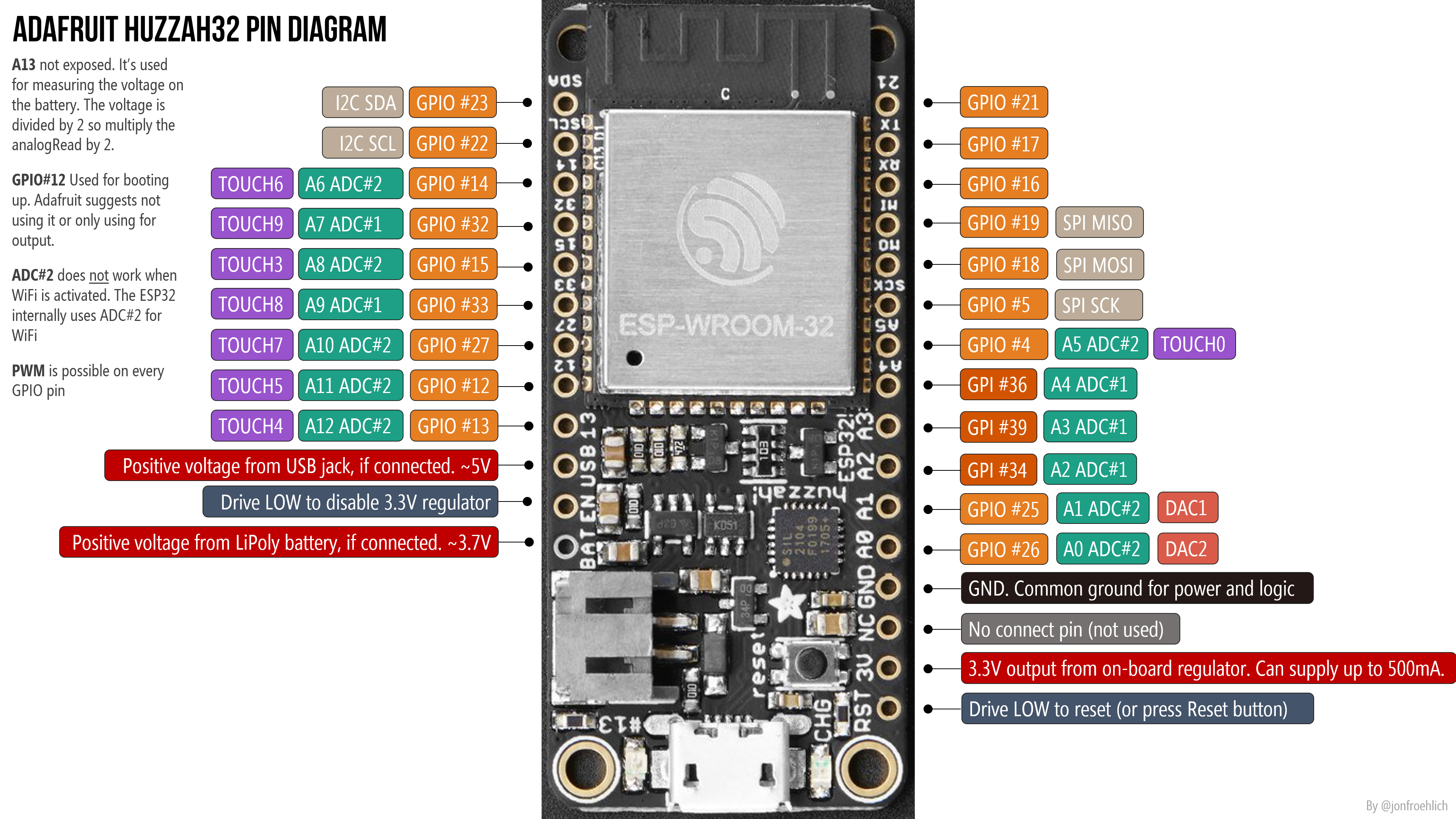
Adafruit HUZZAH32 pinout (Jon Froehlich)
Tools#
- Board: Adafruit HUZZAH32 $19.95
- Test Equipment: Espotek Labrador $29.00
- Breadboard: Half-size breadboard $5.00
- Software: MicroPython Free!
For around $55, you will have a complete kit to write and test code on an extremely powerful microcontroller board, with an extremely capable test setup.
1. Blink#
Of course everything has to start with Blink! In our case, we’ll use the Labrador to observe the signal, its frequency, duty cycle. and amplitude.
Hardware#
For this set of experiments, we’re going to keep things simple and just use the Labrador and the HUZZAH32. I’ve kept the breadboard small as well.
Wiring:#
- Labrador Oscilloscope CH1 (DC) to GPIO13. Orange wire.
- Tie the two grounds together. Black wire.
- Make sure the HUZZAH32 GND pin has a wire to the ground rail as well. White wire.
- DOUBLE-CHECK ALL CONNECTIONS BEFORE PLUGGING IN BOTH USB CABLES!
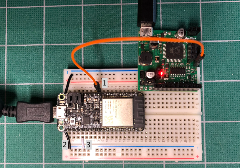
Breadboard with Labrador and HUZZAH32
Software#
Copy and paste this code into the REPL of MicroPython running on the HUZZAH32. If you need help, see this entry.
# ManPinTest.py - blink a defined pin at 5Hz
# identify the pin to be tested
# either by pin i.e; 27
import machine
import time
pin = machine.Pin(13, machine.Pin.OUT)
on_sleep = 100
off_sleep = 200
freq = 1 / (on_sleep + off_sleep) * 1000
duty = on_sleep / (on_sleep + off_sleep) * 100

print(pin, "will have a", freq, "Hz signal with a duty cycle of", duty, "%")

while 1 == 1:
    pin.value(1)
    time.sleep_ms(on_sleep)
    pin.value(0)
    time.sleep_ms(off_sleep)
Labrador Application#
Using the image, below ensure you have set the following parameters:
- Vmax 4V
- Time Window 500ms
- Trigger checked and a 2.80V (value is not critical, something above 1.5V)
- Use right click to set the vertical cursors and measure frequency
- Click to set the horizontal cursors and measure amplitude (not shown)
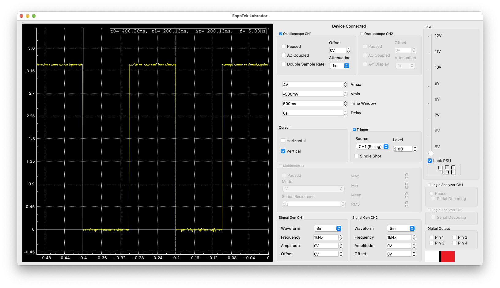
Labrador Application showing ManPinTest
Note that the frequency is 5Hz as stated in the ManPinTest comments. Also note (very important!) that the Amplitude of the signal is only 3.6V, this board can NOT take a 5V signal. Doing so will more than likely, destroy the processor on the board.
Make Changes!#
- Change the time.sleep_ms parameters to change the frequency of the signal. Is your measured frequency, the same as the frequency listed in the serial monitor?
- Make asymmetrical changes to the time.sleep_ms parameters to see a change in duty cycle of the signal. Do you get the same duty cycle? (Duty cycle is defined as % time the signal is on or high.)
- Compare the changes made in 1 and 2 to the brightness of the on-board LED. How does the brightness change when the frequency changes and when the duty cycle changes?
Your blink program is a manual pulse-width modulation (PWM) program. By changing the parameters, changes the signal. Changing them, however, keeping them the same for both, changes the frequency, while making asymmetrical changes will change the duty cycle.
Try commenting out the two time.sleep commands. What happens? On my board I got approximately 31kHz for the frequency. There are two issues that happen here, one, the Labrador is capable of measuring up to about 60kHz and the ESP32 running MicroPython has it its limits. So the signal isn’t clean as it was at the lower frequencies.
Using the Labrador (or any oscilloscope) will provide much more information than watching an LED blink. In fact, what is great is that we can measure what is happening on any pin. Change the pin value on line 7 from 13 to 12. Move the orange wire up (away from the USB connector) one pin. Confirm that this is pin 12 by looking at the diagram at the top of the page. Rerun your program, does it continue to show the same signal? Again, this shows the value of using the Labrador as you can see the signal on the pin without having to use an LED.
Pulse Test#
One last thing…run the PinTest.py program, which is an interactive program to test pins. Be sure to change the orange wire to the pin you are specifiying to test and uncheck Trigger. The Labrador will show when the pin is HIGH, LOW or a BLINK (set the time window to 1s to see the entire pulse).
Running PinTest also allows you to work with the Trigger on the Labrador. For example, change the Blink time (lines 41 and 43) to 50 for 50 msecs. This will provide a narrow pulse. Set the Time Window to 200ms and the Delay to 100ms. Set the Trigger Level to 1.80 (or higher) and ensure Trigger is checked. In the Serial Monitor, type 3 for test 3 and press return. If all goes well, you’ll see an image like this:
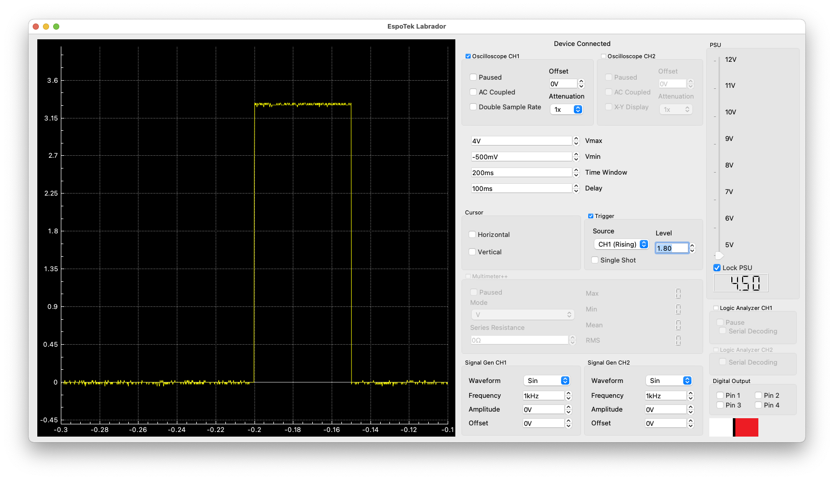
Labrador showing PinTest Pulse
In our next step, we use the ESP32 hardware to provide a PWM signal and use software to control the frequency and duty cycle.