I’ll use this amplifier to perform multiple tests using the Espotek Labrador.
For more information on using operational amplifiers, I encourage you to look at these sources:
- What is an op amp?
- MAS.836 HOW TO BIAS AN OP-AMP
- Avoiding Op-Amp Instability Problems In Single-Supply Applications
Simple Operational Amplifier Discussion#
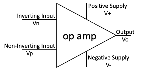
Simple op amp figure (note the voltage names)
- No current flows into the input pins (i.e. infinite input impedance)
- The output voltage will adjust to bring both input pins to the same voltage
Or another way to put it from:
Analog Devices: The Op Amp Basic Operation#
“The basic operation of the op amp…easily summarized…assume…a portion of the output that is fed back to the inverting terminal to establish the fixed gain for the amplifier…is negative feedback.
Any differential voltage across the input terminals of the op amp is multiplied by the amplifier’s open-loop gain…As long as the input and output stays in the operational range of the amplifier, it will keep the differential voltage at zero, and the output will be the input voltage multiplied by the gain set by the feedback.”
And one more comment from
TI: E2E What is an op amp?#
“So that’s the fundamental principle of an op amp: it is only linear when the voltages at the input pins are equal. In order to achieve this, however, an op amp can only adjust its output voltage. Output swing limitations can cause the input voltages to diverge from one another, which yields nonlinear, undesirable behavior.”
We’ll use the Espotek Labrador to confirm the operational range of the amplifier. The design is fairly simple, it is an inverting amplifier with bias and a fixed gain:
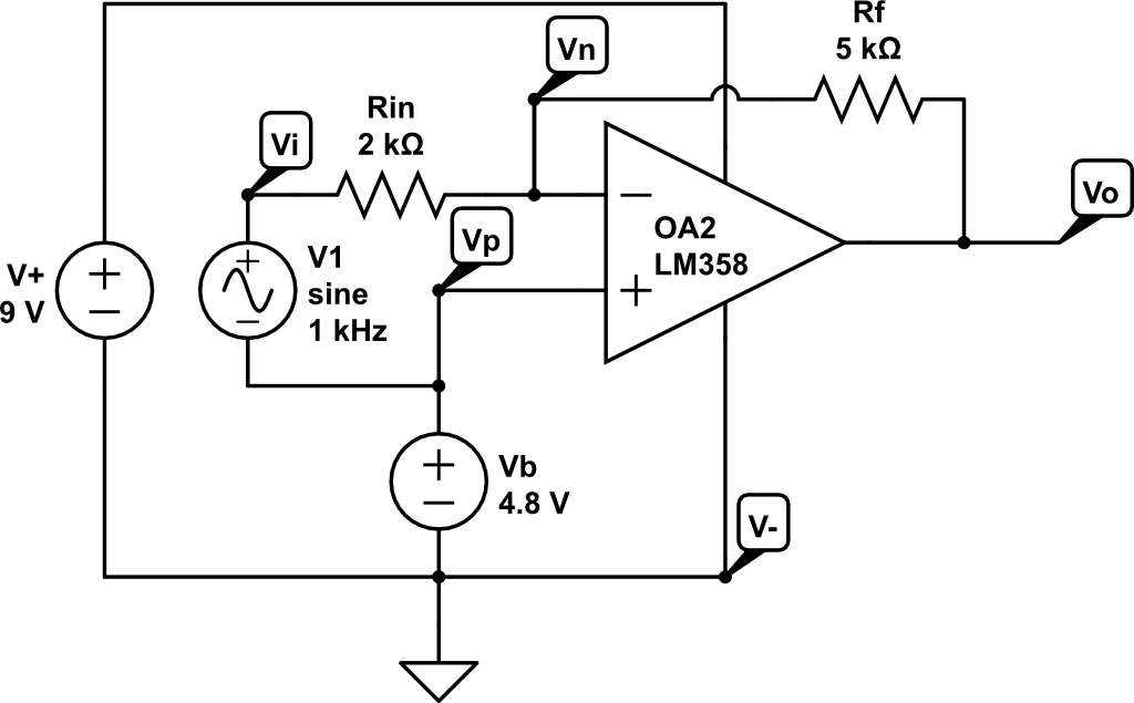
Single-supply, inverting amplifier with bias circuit
As you can see in the circuit diagram, we will be using the LM358, an inexpensive dual op amp design in a 8 pin DIP.
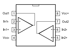
LM358 pinout
- Low Power Dual Operational Amplifiers
- The LM158 series consists of two independent, high gain, internally frequency compensated operational amplifiers which were designed specifically to operate from a single power supply over a wide range of voltages.
- Application areas include transducer amplifiers, dc gain blocks and all the conventional op amp circuits which now can be more easily implemented in single power supply systems. (National Semiconductor)
We’ll also be using it in a single-supply configuration. And we’ll need to have a bias voltage (Vb) in order to ensure the op amp doesn’t go into saturation prematurely. More discussion on why, in the AC Signal analysis. See this article for more great information on op amps and bias voltages: MAS.836 HOW TO BIAS AN OP-AMP
Based on the discussion in the document, we’ve got the following formula:
- (Vi - Vb)/Rin = (Vb - Vo)/Rf or
- Vo = Vb - Rf/Rin(Vi - Vb)
Using the above circuit in CircuitLab, we will get the following DC Sweep diagram:
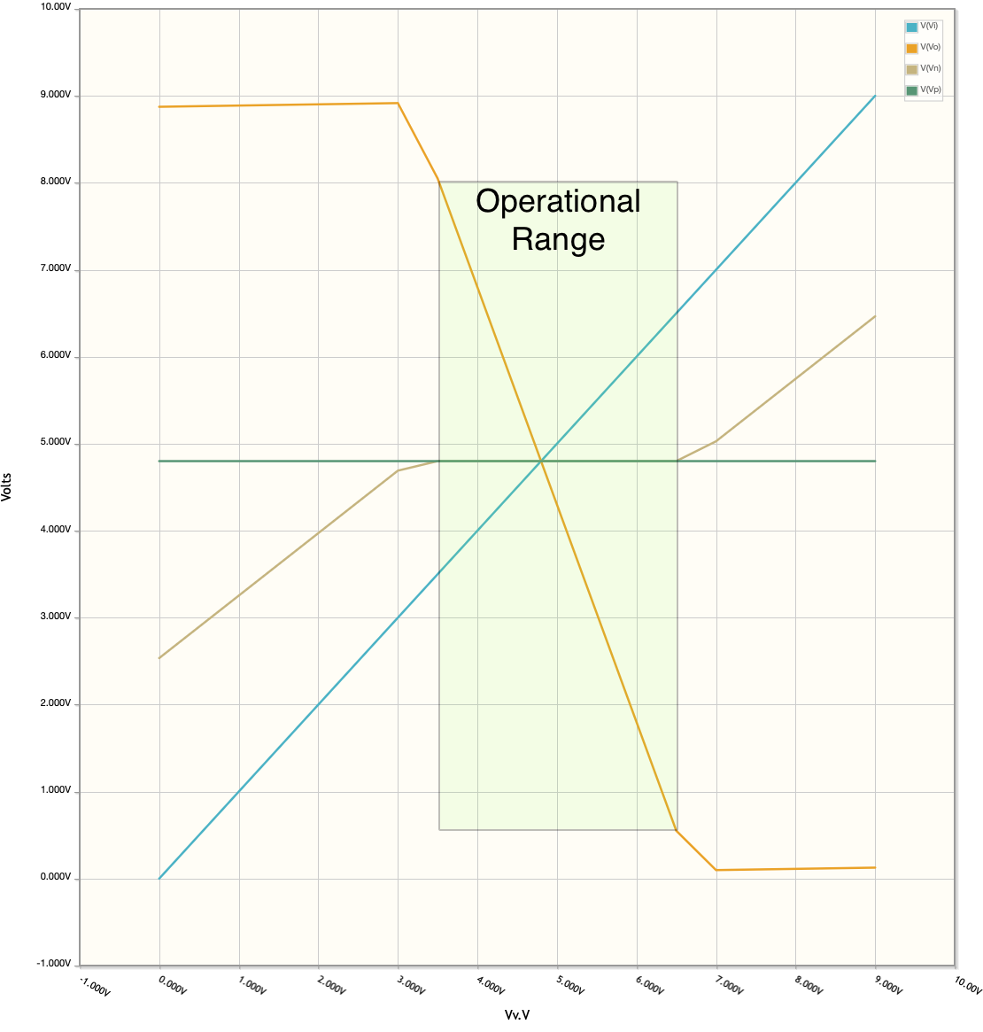
Inverting op amp amplifier circuit graph
- Vi (blue line) goes from 0-9V (we’ll use a potentiometer to do this)
- Vn (brown line) is measured at the inverting input terminal at the op amp. Since we know the non-inverting input is held at 4.8V, when this voltage is also 4.8V we know the opamp is in its operational range.
- Vo (orange line) follows the formula we have above:
- For example, when Vi = 4.8V, Vo = Vb = 4.8V.
- Notice that while Vi is between 3.5V and 6.5V, Vn - Vp = 0, Vo is linear and ranges between 8.05V and 550mV.
Which results in the green box labeled Operational Range.
OK, so what does all this mean?#
The graph clearly shows the original points by both Analog Devices and TI. The fact that while Vn - Vp = 0, the op amp is in it’s operational range. And we see this as Vo is linear and the slope of Vo (calculated) is -2.5, which is the gain of this inverting amplifier.