Where I describe the function - analogWrite().
Introduction#
While analogWrite can be an easy function to use, its not easy to initially understand. This stems from a couple of reasons, first, its mis-named in that the function is not doing anything from an analog perspective and second, it uses a concept called pulse-width modulation (PWM), which in itself is difficult to understand.
Pulse Width Modulation (PWM)#
Lets start with explaining pulse-width modulation. Here is a video where a pulse is being modulated:
This video is showing a sqare wave that is expanding and contracting on the screen.
- Changing the width of a square wave or pulse over time, is called modulation, hence the term, pulse width modulation or PWM.
Why would we need this?#
While there are a lot of applications for PWM, the easiest one to immediately understand is using PWM to reduce the energy used by a LED.
Understanding what the eye can see#
First, let’s understand the impact of frequency on visibility. As a light’s blinking increases in frequency, the eye begins to see it as a constantly lit bulb.
For example, think about our blink program. We turn the LED on for a period of time, then we turn it off. If the combined time on/off is greater than 20ms (or 20/1000 second), chances are we will see flickering as the human eye can discern a frequency of down to about 60Hz or 1/60 or 16/1000 second.
Try it with your blink program, set the on time to 15 and the off time to 15 and are you able to see it blink or flicker? (Its best to try this on an LED plugged into the breadboard, not the on-board LED.)

blink using 15ms on and 15ms off
Note: The image is from an oscilloscope, it shows the voltage on the LED over time. Note the time scale at the bottom of the image, and the voltage on the left hand side.
How to read the image above:
- The period is the length of time it takes for a full cycle, in this case 30 ms
- The frequency is the reciprocal of the period or 33Hz, meaning a full cycle happens 33 times per second or 33Hz
- The positive duty cycle (typically referred to as duty cycle) is the % of time the wave is high, in this case, 15ms of the 30ms or 50%
Now reduce the time to 10 and 10. Does the LED flicker? Maybe a little, or doesn’t seem sharp?
Reduce the time once more, to 5 and 5. Now I don’t believe you are able to see the LED flicker. It is now blinking 100 times per second which is faster than the human eye can discern.

Blink using 5ms on and 5ms off
Note the following:
- Period: 10 ms
- Frequency: 100Hz
- Positive Duty Cycle: 50%
Note that we haven’t changed the width of the pulse, only the number of pulses per second or frequency. And we don’t have much more room to move as we only have the values 1-4 to adjust for on or off time.
And here’s the good news…“since the light is only on 50% of the time, we are saving 50% in electricity costs!”.
Dimming the light#
Now, let’s see if we can dim the LED. Change the on time to 1 and the off time to 4.

Blink using 1ms on and 4ms off
Note: The time scale has been reduced in half to show more detail of the signal
- Period: 5 ms
- Frequency: 200Hz
- Positive Duty Cycle: 20%
What happens to the light of the LED? Is the light still visible? If so, we could save even more energy as we’ve gone from a 50% duty cycle to a 20% duty cycle. Think of it this way, if it costs $10/mo to keep the LED lit at 100%, it would cost $5/mo at 50% and only $2/mo at 20%.
Flip the times, so the on time is 4 and the off time is 1. What happens to the light? Its brighter because we’re now using an 80% duty cycle, which is four times the energy!

Blink using 4ms on and 1ms off
- Period: 5 ms
- Frequency: 200Hz
- Positive Duty Cycle: 80%
We could continue to play with the numbers to see what happens, however, we do have a serious limitation. As the combined times increase, the chance of the LED light to flicker increases, which can be disconcerting.
Try an on time of 5 and an off time of 20, this will still give us a 20% duty cycle with great savings, however what happens to the LED. We can start to see it blink, which is problem.
So what did we learn?
- A light blinking at a frequency above 60Hz appears to the human eye as if it was constantly on.
- By blinking a light, we can reduce the amount of energy the light uses, and this is called decreasing its duty cycle.
PWM Capability of the ATmega328P#
While our blink program worked well, it is cumbersome to adjust the duty cycle. We also face an issue where we don’t have much leeway in adjusting the ratio, for as the numbers increase, the blinking becomes noticeable.
The ATmega328P microcontroller fixes both of these issues by offering PWM capability. The Uno has specific pins marked with a “~” to indicate they are capable of being programmed with a PWM timer. If you look at the board, you will see 6 pins, ~3, ~5, ~6, ~9, ~10, and ~11.
The Arduino framework calls the ability to use the PWM capabilities, analogWrite. The function has two parameters:
- a pin (must be one of the 6)
- the duty cycle, a value between 0-255, where the value/255 equals the duty cycle
Note: Why 255? This is the largest number an 8-bit number may represent. Why not 100? We don’t want to use precious computing cycles to calculate a percentage. We ask the programmer to do that.
When programming the ATmega328P by its registers, the frequency can change dramatically on the pins, however for the purposes of analogWrite() the frequency is limited to 488Hz or 976Hz. This is by design, to simplify the function and ensure, both are well above 60Hz.
So for the purposes of analogWrite(), the only thing which will matter is the duty cycle of the frequency. Meaning…analogWrite() will take a pin and duty cycle as its two arguments, and the desired pin will output either 488Hz or 976Hz at the requested duty cycle.
The AVR_C analogWrite(), is identical in function and asks for a pin number and a duty cycle, value.
Bringing this back to our LED example, using analogWrite allows us to do two things when specifying the duty cycle:
- Reduce the energy used by an LED, in comparison to an LED which is constantly on
- Reduce the light intensity (dim) of an LED compared to an LED which is always on
From a programming perspective, we can change the blink program from:
digitalWrite(LED, HIGH);
delay(5);
digitalWrite(LED, LOW);
delay(5);
to one using analogWrite():
analogWrite(LED, 127);and we get the benefit of easily decreasing the duty cycle, to one which has the LED dim, however still noticeable, reducing our power consumption. In the image below, the LED is quite visible, however, the duty cycle is 12.5%.
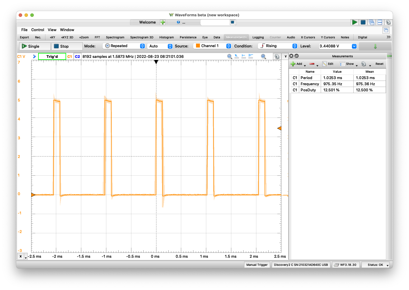
Using analogwrite and a duty cycle parameter of 31
- Period: 1.02ms
- Frequency: 975Hz
- Positive Duty Cycle: 12.5% (as 31/255 = 12.5%)
A Practical Example#
Using PWM to dim an LED and save energy is great, however, it seems like overkill, right? Yes, while it makes a great example as to how to understand the effect of PWM, it doesn’t make a great, practical solution.
A better example of a solution is to think of 3 LED’s in one, called an RGB LED. An RGB LED, combines a red LED, a green LED and a blue LED in one package. The combination of the three LEDs being lit, can create different colors. If only the red LED is lit, the color will be red, however, if it is equal parts, red and green, the color will be yellow. And one can continue to use duty cycle to change the intensity of the colors to get a slightly different color.
The code to light the RGB LED becomes quite simple:
int redPIN = 3;
int greenPIN = 5;
int bluePIN = 6;
# make the LED yellow
analogWrite(redPIN, 127);
analogWrite(greenPIN, 127);
analogWrite(bluePIN, 0);
And by adjusting the percentages, one can achieve a very specific color, for example:
- the combination of 25% red and 75% green, creates a more pleasing yellow than the equal parts combination
- the combination of 12% red, 2% green and 8% blue, makes a more pleasing light purple, than 90%/10%/50% as the LED is not quite as bright and maintains the proper color combination.
A Final Thought#
Imagine changing the LED out and replacing it with a electric motor. And instead of dimming the LED, we are reducing the RPM of the motor. You can quickly see how an electric car uses the concept of PWM to either increase or decrease its speed. It also uses PWM to decrease the power required for an electric motor, increasing its battery life.