Where I use Forth to develop a better understanding of the ATmega328P PWM capabilities. Revised from original post on April 17, 2021
Sources#
Introduction#
Pulse Width Modulation (PWM) is a technique used to control analog circuits using digital signals. It is the capability to change either the frequency or duty cycle of a digital signal. The former is the number of times the signal switches from low to high in a given period of time and the latter, is how long it is either high or low.
The value of using a PWM is it allows you to reduce the power required for driving a load. For example, instead of turning an LED on, you may drive it with a PWM and reduce the power required by 70-80%, enabling using a battery to drive the device.
You can use a PWM to drive a digital circuit (DC) motor and reduce the power required or to control the motor speed. A higher duty cycle results in a higher average voltage and faster motor speed with reduced power consumption as compared to a always on signal.
The PWM capabilities of the ATmega328P are very good. There are two 8-bit counter/timers and 1 16-bit counter/timer, which provide you with the ability to either create a fixed-frequency signal with an adjustable duty cyle or a fixed duty cycle signal with an adjustable frequency.
Documentation#
To understand how the PWM works:
- Read the datasheet, in this example, I’ll review section 16. 16-bit Timer/Counter1 with PWM page 120.
- Play with the registers and watch the results on an oscilloscope.
- Repeat.
Fundamental Concept#
As stated in the introduction, you can either change the frequency (with constant duty cycle) or the duty cycle (with constant frequency) of the signal. The documentation doesn’t explain this explicitly so it helpful to under the following:
The documentation will refer to a value called TOP. This is where the counter will begin to count back down, as in the counter counts from 0-TOP then back down again and it is this counting, which generates a changing signal. When TOP is reached, a pin or bit in a register flips, creating a digital signal.
- If TOP is a fixed number such as hex 0FF, 01FF etc, then the signal becomes a fixed frequency signal where you may adjust the duty cycle.
- If TOP is an adustable number such as one in a register, OCRA, then the signal is a fixed duty cyle (50%), with an adjustable frequency.
It will be helpful to refer back to these two definitions as your are working with the ATmega328P Timer/Counters.
Datasheet#
It is helpful to know which pins are controlled by a specific Timer/Counter. For this example, I’ll use the highlighted pins D9 and D10 of Timer/Counter 1.
|
|
For Timer/Counter 1, I started here: (It’s helpful to note the page numbers in the datasheet.)
\ Timer 1 definitions pgs 140-166 DS40002061B
\ TCCR1A [ COM1A1 COM1A0 COM1B1 COM1B0 0 0 WGM11 WGM10 ]
\ TCCR1B [ ICNC1 ICES1 0 WGM13 WGM12 CS12 CS11 CS10 ]
Timer/Counter 1 Fast PWM
Above is the table from the datasheet. Notice a couple of things:
- While Fast PWM has five modes, 5, 6, 7, 14, or 15, to be able to use both pins 9 and 10, I’ll only do modes 5, 6, 7. From DS page 140 “WGM13:0 = 14 or 15: Toggle OC1A on Compare Match, OC1B disconnected (normal port operation).”
- When doing so, the TOP is set to one of three values 0x00FF, 0x01FF, or 0x01FF. Which means the frequency of the signal will be fixed, and I will be able to adjust the duty cycle. I am able to set the frequency by selecting one the clock scalars 1, 8, 64, 256, 1024.
Play#
Once I started playing with the registers and watching the results on the scope, I realized the PWM could be simplified to:
- Fast PWM WGM13:0 = 5, 6, 7
- Again, use both OC1A and OC1B, WGM13:0 = 5, 6, 7 so WGM13 is 0
- WGM12 remains 1, while WGM1:0 range from 1-3 and control the resolution of the counter (8,9,10 bits)
- The frequency can be easily controlled by CS2:0 1-5 (clock scalars 1, 8, 64, 256, 1024)
Which meant these parameters will control the PWM:
- frequency - (1-5) defining the scalar for the frequency of the PWM
- resolution - (1-3) resolution of the counter, 8, 9 or 10 bits
- dcA - duty cycle numerator of pin 9 (OC1A) duty cycle = dcA/resolution
- dcB - duty cycle numerator of pin 10 (OC1B)
And by writing a word which stores those parameters appropriately will create a PWM based on Timer 1 using Fast PWM (single-slope operation):
: FPWM_1 ( freq res dcA dcB -- )
  OCR1BL ! \ n/resolution dcB
  OCR1AL ! \ n/resolution dcA
  %10110000 + TCCR1A c! \ COM1A1 COM1B1 res
  %00001000 + TCCR1B c! \ WGM12 freq
  D9 output
  D10 output
;
Identify the Values#
Using this word and entering different values for frequency, resolution and duty cycle I was able to cycle through 15 different frequencies, all with a duty cycle between 0-100%. The more I played and explored the PWM, I realized I could simplify the interface even more. The resolution defined the frequency, so there wasn’t value in keeping them separate. The resolution also defined the range for the duty cycle, however, I didn’t see value in creating a check to determine if the value was in range. Nor did I see value in checking if there were two duty cycle values.
This left me with an interface which could use these constants:
\ 8-bit resolution => duty cycle n/255
1 1 2constant 62K_8
2 1 2constant 8K_8
3 1 2constant 975_8
4 1 2constant 244_8
5 1 2constant 60_8

\ 9-bit resolution => duty cycle n/512
1 2 2constant 31K_9
2 2 2constant 4K_9
3 2 2constant 488_9
4 2 2constant 122_9
5 2 2constant 30_9

\ 10-bit resolution => duty cycle n/1023
1 3 2constant 16K_0
2 3 2constant 2K_0
3 3 2constant 244_0
4 3 2constant 61_0
5 3 2constant 15_0
Using the constants, made the values self-documenting. One, you knew what the frequency would be and the last digit defined the range for the duty cycle, 8-bits, 9-bits, or 0 (for 10-bits). So the final usage would be something like this:
62K_8 63 127 FPWM_1 \ 62.4KHz, 25% duty cycle on Pin 9, 50% positive duty cycle on Pin 10 (image below)
4K_9 127 255 FPWM_1 \ 3.9KHz, 25% positive duty cycle on Pin 9, 50% duty cycle on pin 10 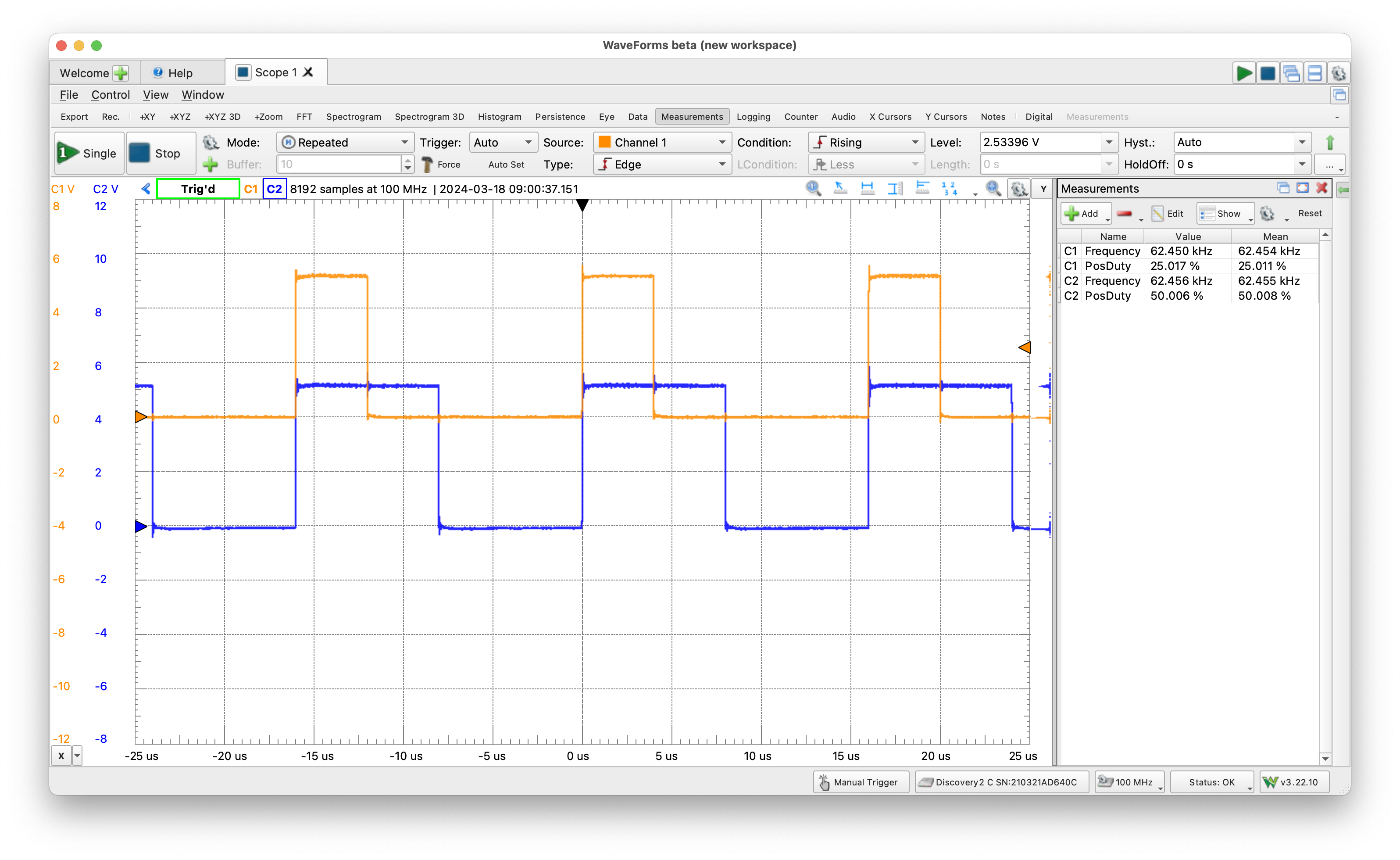
62.4KHz, 25% duty cycle on Pin 9 (orange), 50% positive duty cycle on Pin 10 (blue)
Final Thoughts#
Duplicating this effort for Timer/Counter 0 and Timer/Counter 2 would be extremely easy as neither T/C has the resolution variable to worry about. The frequency is determined solely by the input scalar.
I believe this approach is much more simple and more powerful than analogWrite(duty cycle) of the Arduino framework as it allows one to choose a frequency along with the duty cycle of the signal.
Notes#
For additional Timer/Counter 1 examples see AVR_FF, in the Library there are files which stand alone and setup Timer/Counter 1 and 2:
- T1_CTC - 16.9.2 Clear Timer on Compare Match (CTC)
- T1_FPWM - 16.9.3 Fast PWM Mode
- T1_PWMPC - 16.9.4 Phase Correct PWM Mode
- T2_MS - 18.7.4 Phase Correct PWM Mode (millisecond counter)
- T2_FPWM - 18.7.3 Fast PWM Mode