Where I demonstrate how to begin to program the RP2040 (Pi Pico and Pi Pico W) using Micropython.
Introduction#
I already have quite a few entries on Micropython. While I’ve experimented with multiple boards using the language, ESP32, FIDI, and the Adafruit Feather RP2040, this entry begins a set of entries on using Micropython as a development language with the Pi Pico W as the development microcontroller. The cost ($6) of the Pico W, with it’s computing power and wireless capability coupled with the ease of development of Micropython, makes this combination compelling.
1. Documentation#
Books#
I highly recommend having documentation to help you on this journey. These two books are free and are extremely valuable.
Action: Download them and have them available on your computer.
- Raspberry Pi Pico Python SDK
- Get Started with MicroPython on Raspberry Pi Pico [Search for book title on site, if link does not work.]
Links#
In addition to the books above, the following links will be important.
Action: Bookmark these links them and have them available in your browser.
- Pico W Pinout
- MicroPython home
- MicroPython documentation
- MicroPython Pi Pico W download
- Code for this page on GitHub
2. Tool Chain#
Install the following tools, as all of my examples will use them.
Action: Install all items from steps 1-3 appropriate to your computer’s operating system.
2.1. Multi-platform, install the appropriate version
- Sublime Text - multi-platform code editor, will be the code editor used in this series
- CoolTerm - multi-platform serial monitor ONLY DOWNLOAD FROM THIS SITE: https://freeware.the-meiers.org/ For more information, go here.
- Python 3 - Use the official installer for both Windows and macOS
2.2. Windows-specific:
- Git for Windows - This will provide both the Command Line Interface (CLI) for Windows (git-bash) and version control, git
2.2. macOS-specific
- For command line interface (CLI), use Apple’s Terminal program
- Homebrew - Use the homebrew installer for macOS to install git
# install Homebrew per instructions on site brew.sh
# install git for version control
brew install git
2.3. Multi-platform, once Python is installed Once Python is installed use pip to install:
3. MicroPython Installation#
Action, perform the following two steps:
3.1. Install a RESET button#
For ease of use, I recommend the following steps:
- Install header pins or purchase your Pico W with header pins.
- Plug your board into a breadboard.
- Create GND rails [See Note:] on your breadboard by connecting wires (gray wires in image) from a GND pin on the Pico to the blue “-” rail on the breadboard. (I use pin 3 on one side and pin 38, on the other side).
- Plug a push button spanning the center channel into your bread board at the end of the Pico
- Connect a wire (gray wire in image) into one end of the push button to GND
- Connect a wire (blue wire in image) into the breadboard row diagonally opposite the GND connection to pin 30 RUN on the Pico.

Pico W with Reset button
Note: The value of creating GND rails, is that it makes it easy to ground other components as you extend the functionality of your Pico with hardware. The blinkenleds are a good example below.
3.2 Install MicroPython#
Download#
To use MicroPython on the Pico, you must download the UF2 file which contains MicroPython for the Pico W. It can be found under Firmware, on the link above (…Pico W download). If you want the code discussed in this entry, you may download it here.
USB Mode#
Having a reset button enables you to easily put the PICO W into USB mode. With a USB cable plugged between your PICO and your computer:
- Press and hold the BOOTSEL button on the Pico W.
- Press and release your reset button
- Release BOOTSEL.
Your board will show up on your computer as a USB drive labeled RPI-RP2. If the board doesn’t show up, check your connections to the Reset button.
- Is there a wire from GND on the Pico to the GND rail on the breadboard?
- Is there a wire from the GND rail on the breadboard to the button?
- Is there a wire from pin 30 RUN to the button?
- Are the connections to the button diagonally opposite? (as compared to straight across)
- Did you follow the 3-step sequence above exactly? The timing is critical.
Drag and Drop#
Now drag the .uf2 file you downloaded from the MicroPython site and drop it on the USB drive RPI-RP2. It will take several seconds to copy the 1MB+ size file on to the Pico and the board will restart, automatically ejecting itself from the computer. (For which the computer might complain, however, its not a big deal.)
3. Test Using Read-Evaluate-Print-Loop (REPL)#
For this step, you will only need CoolTerm and your Pico W plugged into your computer. MicroPython needs to be loaded on to your Pico W and you will need to know the serial port to which your Pico W is connected.
CoolTerm provides you a selection of ports, where its fairly easy to guess which one. As you can see from the image below, there are two ports available, one with Bluetooth and one with a number. It is the latter port which will be the one required to communicate with the Pico W. Windows computers will show a port name with a COM such as COM3 or COM4, you might have to try each port until you get the right one.
You will also need to set the baudrate to 115200. It is best to also set Data Bits to 8, Parity to None and Stop Bits to 1 as shown in the image.
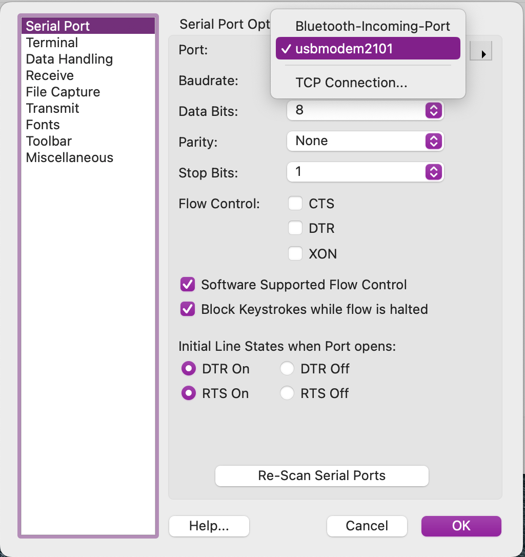
CoolTerm Options Showing Serial Choices
Serial Monitor#
A nice advantage of Python is to be able to test out snippets of code using Read-Evaluate-Print-Loop (REPL). Once you have completed the steps above (select port, set baudrate in CoolTerm) In CoolTerm, press Ctrl-B and you will be greeted by the REPL prompt:
MicroPython v1.21.0 on 2023-10-06; Raspberry Pi Pico W with RP2040
Type "help()" for more information.
>>>
The "»>" indicates we are in the REPL and entering help() would be a great idea!
Welcome to MicroPython!

For online docs please visit http://docs.micropython.org/

For access to the hardware use the 'machine' module.  RP2 specific commands
are in the 'rp2' module.

Quick overview of some objects:
  machine.Pin(pin) -- get a pin, eg machine.Pin(0)
  machine.Pin(pin, m, [p]) -- get a pin and configure it for IO mode m, pull mode p
    methods: init(..), value([v]), high(), low(), irq(handler)
  machine.ADC(pin) -- make an analog object from a pin
    methods: read_u16()
  machine.PWM(pin) -- make a PWM object from a pin
    methods: deinit(), freq([f]), duty_u16([d]), duty_ns([d])
  machine.I2C(id) -- create an I2C object (id=0,1)
    methods: readfrom(addr, buf, stop=True), writeto(addr, buf, stop=True)
             readfrom_mem(addr, memaddr, arg), writeto_mem(addr, memaddr, arg)
  machine.SPI(id, baudrate=1000000) -- create an SPI object (id=0,1)
    methods: read(nbytes, write=0x00), write(buf), write_readinto(wr_buf, rd_buf)
  machine.Timer(freq, callback) -- create a software timer object
    eg: machine.Timer(freq=1, callback=lambda t:print(t))

Pins are numbered 0-29, and 26-29 have ADC capabilities
Pin IO modes are: Pin.IN, Pin.OUT, Pin.ALT
Pin pull modes are: Pin.PULL_UP, Pin.PULL_DOWN

Useful control commands:
  CTRL-C -- interrupt a running program
  CTRL-D -- on a blank line, do a soft reset of the board
  CTRL-E -- on a blank line, enter paste mode

For further help on a specific object, type help(obj)
For a list of available modules, type help('modules')
>>>
Test example#
Practice by typing the lines highlighted (lines 1, 3 and 4). Lines 5-7 are returns, simply press return 4 times starting with line 4. Don’t type the “>>>” or the “…” as those are the prompts for the REPL. When you press return, four times, after entering the print statement, the loop statement will execute.
|
|
Anytime where you are confused as to how to use a command or section of code, it is a good practice to test it using the REPL. You can type it in or use paste mode (below) to enter the code into the REPL.
Paste Mode#
In this section, you will need to open your code editor (this example uses ST4), keep CoolTerm open and have your Pico W plugged into your computer.
Editors#
As recommended above, I am using the cross-platform programmer’s editor, called Sublime Text. I highly recommend it and it will be used for all of the examples. If you’re wanting to learn how to program for the long-term, it is a very good code editor. In the next entry, I will show how to automate Sublime Text to enable you to be very efficient.
Other programming editors which would work well are Notepad++ on Windows, BBEdit on macOS or Kate on Linux. I do NOT recommend beginning programming using Microsoft’s VS Studio or VS Studio Code. These are Integrated Development Environments (IDE), and their complexity will reduce your efficiency and ability to learn the Python language quickly.
Using Paste Mode#
For simple programs, the steps for paste mode are:
- To enter paste mode, press Ctrl-E while in the REPL
- Select and copy all of the text you wish to execute in your code editor
- Paste it in the REPL window in the serial monitor.
- Press Ctrl-D to exit paste mode
blink Example#
We will start with the classic blink program. This version of blink is slightly more complicated than the typical blink. It allows you to use the program via an import method, which is valuable in debugging. It is my standard form of blink. Copy and paste the code below into ST4. This allows you to edit the code when desired.
from machine import Pin
import time


def Blink():
    led = Pin("LED", Pin.OUT)

    while True:
        led.toggle()
        time.sleep_ms(250)


if __name__ == '__main__':
    Blink()
Now copy and paste the code from ST4 using the Paste mode described above…Ctrl-E to enter Paste mode, paste then Ctrl-D to exit.
It will need to look like the image directly below:
paste mode; Ctrl-C to cancel, Ctrl-D to finish
=== from machine import Pin
=== import time
===
===
=== def Blink():
===     led = Pin("LED", Pin.OUT)
===
===     while True:
===         led.toggle()
===         time.sleep_ms(250)
===
===
=== if __name__ == '__main__':
===     Blink()
===
Once you hit Ctrl-D to complete the transfer, the program will begin to execute. In this situation, the Pico W LED began to blink. You will need to press Ctrl-C to regain control of the Pico W. We will fix this in the next iteration of blink.
In ST4, change the value 250 on line 10, to a larger value. Copy and paste the entire program again, using Paste mode. Does the blink rate slow down?
Continue to try a couple of different values on line 10 and use Paste mode to test them. It will help you understand how to use this valuable technique.
Example Programs#
blink_key#
This version of blink allows you to press any key to regain control of the Pico W. This is a valuable technique which you might want to use in other programs. Copy the program below into a new file in ST4, then copy and paste it using Paste mode into the Pico W.
# blink_key - a blocking blink for built-in led and will stop on any key press
from machine import Pin
import time
import sys
import uselect


spoll = uselect.poll()
spoll.register(sys.stdin, uselect.POLLIN)


def read1():
    return(sys.stdin.read(1) if spoll.poll(0) else None)


def Blink():
    led = Pin("LED", Pin.OUT)
    key = read1()

    while key is None:
        led.toggle()
        time.sleep_ms(1000)
        key = read1()
    led.value(0)
    return


if __name__ == '__main__':
    Blink()
    sys.exit()
Are you able to stop the blinking using any key on the keyboard?
echo_hex#
This program will accept any key input and will print the key, the decimal ASCII value of the key and the hexadecimal ASCII value of the key. This can be of value when you are testing a program which uses key input. Sometimes its of value to know the ASCII values.
# echo_hex - print the hex equivalent of key pressed
import sys
import time
import uselect


spoll = uselect.poll()
spoll.register(sys.stdin, uselect.POLLIN)


def read_1char():
    return(sys.stdin.read(1) if spoll.poll(0) else None)


def show_key():
    key = read_1char()
    while key is None:
        key = read_1char()
    print(f"key: {key} dec: {ord(key)} hex: {hex(ord(key))}")
    return


if __name__ == '__main__':
    time.sleep(1)
    i = 0
    while i < 5:
        print(f"Press a key: ", end='')
        show_key()
        i += 1
    print(f"Returning to system prompt")
    sys.exit()
The output will look like this:
Press a key: key: 1 dec: 49 hex: 0x31
Press a key: key: 2 dec: 50 hex: 0x32
Press a key: key: 3 dec: 51 hex: 0x33
Press a key: key: 4 dec: 52 hex: 0x34
Press a key: key: 5 dec: 53 hex: 0x35
Returning to system prompt
>>>
I included this program as part of the copy/paste examples, as it is a good test of the serial interface.
Once you feel comfortable with paste mode, go to RP2040 MicroPython: Developing Applications to begin more advanced program creation.