Where I compare the execution speeds of different combinations of boards and languages. I will continue to update this post with other languages and processor combinations.
Table for the impatient#
| ucontroller/Speed(MHz) | Method* | frequency | Language |
|---|---|---|---|
| ATSAMD21/48Mhz | Integral | .6kHz | CircuitPython |
| ATSAMD21/48Mhz | Integral function | .7kHz | CircuitPython |
| ATSAMD21/48Mhz | Library | .7kHz | CircuitPython |
| RP2040/133Mhz | Integral function | 1.0kHz | CircuitPython |
| RP2040/133Mhz | Library | 1.44kHz | CircuitPython |
| ATmega328/16MHz | struct/function pointer | 6.1kHz | Arduino C++ |
| ATmega328/16MHz | words in an infinite loop | 27KHz | FlashForth |
| ATmega328/16MHz | struct/function pointer | 55kHz | C |
| ATmega328/16MHz | struct/function pointer | 56kHz | Arduino C++ w/ native toggle |
| ATmega328/16MHz | Assembly language toggle | 108kHz | FlashForth |
| ATmega328/16MHz | Assembly language toggle inlined | 444kHz | FlashForth |
| RP2040/133Mhz | struct/function pointer | 578.7kHz | C |
| RP2040/133Mhz | words in an infinite loop | 2.841 MHz | Mecrisp Forth |
| *See text for an explanation of method. |
Introduction#
While writing about CircuitPython and the FIDI board, I was curious as to the execution speed of CircuitPython on a extremely powerful (relative to the AVR ATmega328) ARM M0+ microcontroller. The M0+ is a modern RISC 32-bit processor with a considerable amount of memory, while the ATmega is 20 year old RISC 8-bit processor with a limited amount of memory. That said, one can’t run CircuitPython on ATmega processors, one must use C or Forth.
To better understand the execution speed trade-offs, I developed a simple program which would cycle through 8 processes using a simple round-robin scheduling algorithm. My goal was NOT to extract the greatest performance on the board as it was to use a simple, yet powerful approach to microcontroller multi-tasking to determine performance.
The simple round-robin scheduling program was 100 times faster running on the ATmega328 in C, than it was in CircuitPython on the ARM M0+ chip. I’ll explore the execution speeds of different chips and languages using the same algorithm.
Why#
When developing a project, its important to understand the tradeoffs which need to be made. Development time and debugging effort can be as important as execution speed. For example, Python(Micropython/CircuitPython) has a REPL which can accelerate development by immediate interaction and C (Arduino C++/C) can decrease debugging time due to the ease of hardware debugging. Python also has a lovely and easy to use development tool chain (Mu), while the Arm GNU C tool chain along with the C SDK required, can be a real pain to install (and use).
Finally, the goal of what you want to accomplish is ultimately what you want to consider in examining board/language combinations. If execution speed isn’t critical, for example, blinking Neopixels on a wearable, CircuitPython is perfect! However, if you are attempting to create something which requires millisecond response time (machine to machine interaction), you will want to consider using C or Forth.
Disclaimer#
My goal wasn’t to find the absolute fastest combination nor was it to determine the fastest method in a specific language. My goal was to determine relative speeds for a language/board combination, in the hopes it might help someone understand when a combination might work or not, due to execution-speed constraints.
The Algorithm#
We’ll want to accomplish three tasks in our algorithm:
- Setup pins as output
- Define 8 tasks to each toggle a specific pin
- Cycle through each task, such that each task executes then returns to scheduler
Execution Speed Tests#
CircuitPython on the ARM M0+ (FIDI)#
Running this test in CircuitPython was interesting as there are several ways to do it. And each one, can slightly increase the speed of execution. Let’s start with the fundamental task code:
# simple round-robin scheduler to test speed
# as the FIDI board only has nine pins available
# uses 8 tasks to make it easy to compare to other boards/languages
import time
import board
from digitalio import DigitalInOut, Direction

PIN0 = DigitalInOut(board.D0)
PIN0.direction = Direction.OUTPUT
PIN0.value = True
PIN1 = DigitalInOut(board.D1)
PIN1.direction = Direction.OUTPUT
PIN1.value = True
PIN2 = DigitalInOut(board.D2)
PIN2.direction = Direction.OUTPUT
PIN2.value = True
PIN3 = DigitalInOut(board.D3)
PIN3.direction = Direction.OUTPUT
PIN3.value = True
PIN4 = DigitalInOut(board.D4)
PIN4.direction = Direction.OUTPUT
PIN4.value = True
PIN5 = DigitalInOut(board.D5)
PIN5.direction = Direction.OUTPUT
PIN5.value = True

RED = DigitalInOut(board.LED_R)
RED.direction = Direction.OUTPUT
RED.value = True
GREEN = DigitalInOut(board.LED_G)
GREEN.direction = Direction.OUTPUT
GREEN.value = True

def t0():
    PIN0.value = not PIN0.value

def t1():
    PIN1.value = not PIN1.value

def t2():
    PIN2.value = not PIN2.value

def t3():
    PIN3.value = not PIN3.value

def t4():
    PIN4.value = not PIN4.value

def t5():
    PIN5.value = not PIN5.value

def t6():
    RED.value = not RED.value

def t7():
    GREEN.value = not GREEN.value

task_list = (t0, t1, t2, t3, t4, t5, t6, t7)
Very simple code which accomplishes the first two steps. The third step can be accomplished in one of three ways, all shown in the same code block below:
|
|
Comparison#
| Method | frequency of toggle |
|---|---|
| Integral | 490Hz |
| Integral function | 704Hz |
| Library | 700Hz |
While it surprises me that running the file as a pre-compiled library file is slightly slower than as an integral function. My biggest takeaway is that keeping the “main” part of the program as short as possible, will result in the fastest execution speed. Overall, I’m surprised that CircuitPython ran so slowly, this is on a 32-bit processor running at 48MHz!
CircuitPython on RP2040#
I ran the same code on the Pico board which uses the Raspberry Pi RP2040 chip. The chip uses the same ARM M0+ processor, however, it runs at 133MHz. In this case, the Pico board ran the Library function routine at 1.44kHz and the Integral Function version at 1.03KHz.
C on the ATmega328P#
Switching languages and significantly switching processors, we’ll look at a comparable algorithm written in C, then compiled/linked/loaded on the 8-bit Atmel AVR ATmeg328P which runs at 16MHz.
C Code for Algorithm#
/* One line kernal for multitasking
*  https://www.embedded.com/a-multitasking-kernel-in-one-line-of-code-almost/
*  Uses direct pin manipulation using a set bit on Input Port
*/

#include <avr/io.h>
#include "delay.h"
#define NTASKS 8

// Uno pin numbers
const uint8_t LED0 = 2;
const uint8_t LED1 = 3;
const uint8_t LED2 = 4;
const uint8_t LED3 = 5;
const uint8_t LED4 = 6;
const uint8_t LED5 = 7;
const uint8_t LED6 = 0;
const uint8_t LED7 = 1;

typedef struct task {
   void (*TickFct)();    // Function to call for task's tick
} task;

task tasks[NTASKS];

void t0 (void) {
    /* toggle led on and off */
    PIND |= _BV(LED0);
    return;
}

void t1 (void) {
    /* toggle led on and off */
    PIND |= _BV(LED1);
    return;
}

void t2 (void) {
    /* toggle led on and off */
    PIND |= _BV(LED2);
    return;
}

void t3 (void) {
    /* toggle led on and off */
    PIND |= _BV(LED3);
    return;
}

void t4 (void) {
    /* toggle led on and off */
    PIND |= _BV(LED4);
    return;
}

void t5 (void) {
    /* toggle led on and off */
    PIND |= _BV(LED5);
    return;
}

void t6 (void) {
    /* toggle led on and off */
    PINB |= _BV(LED6);
    return;
}

void t7 (void) {
    /* toggle led on and off */
    PINB |= _BV(LED7);
    return;
}


int main(void)
{
    DDRD |= _BV(LED0) | _BV(LED1) | _BV(LED2)  | _BV(LED3) | _BV(LED4) | _BV(LED5);
    DDRB |= _BV(LED6) | _BV(LED7) ;

    uint8_t i = 0;
    tasks[i].TickFct = &t0;
    ++i;
    tasks[i].TickFct = &t1;
    ++i;
    tasks[i].TickFct = &t2;
    ++i;
    tasks[i].TickFct = &t3;
    ++i;
    tasks[i].TickFct = &t4;
    ++i;
    tasks[i].TickFct = &t5;
    ++i;
    tasks[i].TickFct = &t6;
    ++i;
    tasks[i].TickFct = &t7;

    for (;;)
    {
    for (int8_t taskcount=0; taskcount < NTASKS; ++taskcount)
        {
            tasks[taskcount].TickFct();
        }
    }
    return(0);
}
This C code ran at 54.4kHz, which is 38 times faster than the Pico and 50 times faster than the FIDI, both running CircuitPython.
Using the Arduino Framework#
As I’m using an Arduino Uno to perform the C testing, it makes sense to also use the Arduino framework and check the speed. The code needed to be tweaked abit to address C++ issues with scope (in this case, the task initialization needed to be performed in a function).
#define NTASKS 8

void t0 (void) {
    /* toggle led on and off */
    digitalWrite(2, !digitalRead(2));
    return;
}

void t1 (void) {
    /* toggle led on and off */
    digitalWrite(3, !digitalRead(3));
    return;
}

void t2 (void) {
    /* toggle led on and off */
    digitalWrite(4, !digitalRead(4));
    return;
}

void t3 (void) {
    /* toggle led on and off */
    digitalWrite(5, !digitalRead(5));
    return;
}

void t4 (void) {
    /* toggle led on and off */
    digitalWrite(6, !digitalRead(6));
    return;
}

void t5 (void) {
    /* toggle led on and off */
    digitalWrite(7, !digitalRead(7));
    return;
}

void t6 (void) {
    /* toggle led on and off */
    digitalWrite(8, !digitalRead(8));
    return;
}

void t7 (void) {
    /* toggle led on and off */
    digitalWrite(9, !digitalRead(9));
    return;
}

typedef struct task {
   void (*TickFct)();    // Function to call for task's tick
} task;

task tasks[NTASKS];

void setup() {
    for (uint8_t i=0;i<NTASKS;i++) {
        pinMode(i, OUTPUT);
    }

    uint8_t i = 0;
    tasks[i].TickFct = &t0;
    ++i;
    tasks[i].TickFct = &t1;
    ++i;
    tasks[i].TickFct = &t2;
    ++i;
    tasks[i].TickFct = &t3;
    ++i;
    tasks[i].TickFct = &t4;
    ++i;
    tasks[i].TickFct = &t5;
    ++i;
    tasks[i].TickFct = &t6;
    ++i;
    tasks[i].TickFct = &t7;

}

void loop() {
    for (uint8_t taskcount=0; taskcount < NTASKS; ++taskcount)
        {
            tasks[taskcount].TickFct();
        }
}
And the resulting code ran at 6.1kHz. There isn’t a toggle function in the Arduino framework, which is unfortunate as it is so easy to do on the ATmega328. Using the toggle command from my C program PIND |= _BV(LED0);, changed the frequency to one slightly faster than that of the C code at 56.4kHz.
Note: I did find using PINB (input port B) on the Arduino a bit wonky, while the same toggle code works well on the Uno using C, it doesn’t toggle correctly using the Arduino framework.
Forth on the Uno#
This was the most absurdly easy one to write. It took me less than 5 minutes…
\ Testing execution speed with round-robin tasking

\ 1. Setup pins as output
: setup
    D2 output
    D3 output
    D4 output
    D5 output
    D6 output
    D7 output
    D8 output
    D9 output
;

\ 2. Define 8 tasks, each to toggle a specific pin
: task0 D2 toggle ;
: task1 D3 toggle ;
: task2 D4 toggle ;
: task3 D5 toggle ;
: task4 D6 toggle ;
: task5 D7 toggle ;
: task6 D8 toggle ;
: task7 D9 toggle ;

\ 3. Cycle through each task

: alltasks
    setup
        begin
            task0
            task1
            task2
            task3
            task4
            task5
            task6
            task7
        again
;
The code ran at 26.5kHz, about half that of the C compiled version. What I believe is most important of this specific example is that the Forth program was developed in the shortest time, while being the second fastest in execution speed. I also believe it is the easiest to immediately understand and begin to make changes.
I replaced the task list in alltasks with the actual commands to determine the overhead consumed by the task call. In other words, I replaced alltasks above with:
: tasksm
    setup
        begin
            D2 toggle
            D3 toggle
            D4 toggle
            D5 toggle
            D6 toggle
            D7 toggle
            D8 toggle
            D9 toggle
        again
;
And the results were surprising. The task call consumed only 1.5us of overhead (approximately 24 clock cycles) as illustrated by this image:
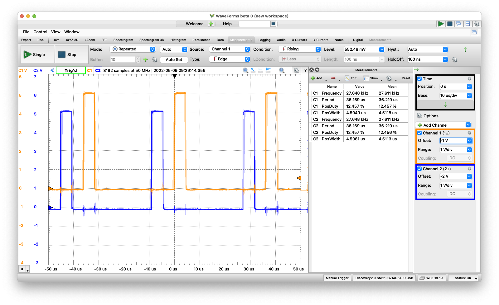
FlashForth running tasks via direct execution
Using a task call in the original version, each task executed every 37.718us, while when the task call was replaced by the task itself (code immediately above) the task was executed every 36.219us.
Forth on the Uno with Assembly Language#
The author of FlashForth, Mikael Nordman, made a comment below regarding the performance of FlashForth. As in “flashforth program could also be optimized quite a bit with inlining and toggling the pin in assembler”. Which I did. The program below replaces the Forth words for toggling the pin, with assembly language code, assembled by Forth. In other words, Forth can easily run AVR assembly language by adding the Forth assembler and uses the proper nomenclature. The optimized program looks like this:
\ Testing execution speed with round-robin tasking
$0003 constant pinb-io  \ IO-space address
$0009 constant pind-io  \ IO-space address

\ 1. Setup pins as output
: setup
    D2 out
    D3 out
    D4 out
    D5 out
    D6 out
    D7 out
    D8 out
    D9 out
;

\ 2. Define 8 tasks, each to toggle a specific pin
: task0 [ pind-io #2 sbi, ] ;
: task1 [ pind-io #3 sbi, ] ;
: task2 [ pind-io #4 sbi, ] ;
: task3 [ pind-io #5 sbi, ] ;
: task4 [ pind-io #6 sbi, ] ;
: task5 [ pind-io #7 sbi, ] ;
: task6 [ pinb-io #0 sbi, ] ;
: task7 [ pinb-io #1 sbi, ] ;

\ 3. Cycle through each task

: alltasks
    setup
        begin
            task0
            task1
            task2
            task3
            task4
            task5
            task6
            task7
        again
;
The program remained easy to write, it was a simple task to replace the toggle word with the proper assembly language. This doubled the speed of execution to 108kHz, as shown in the table above. Which is impressive, given Forth gives you a REPL along with this speed!
There is one more trick…we can try. We can use the word inlined, which ensures the words are “inline in code”, as compared to “called”. We do this by appending the word “inlined” after each definition (see example below). When we do this, we quadruple the speed to 444kHz or 1.12us loop time. With 1.12 microseconds between when a task toggled the bit high then went it toggled the bit low. Let’s analyze the overhead.
- With a 16Mhz clock, 1.12us is 18 clock cycles.
- toggle consumes 1 clock cycle * 8 = 8
- begin/again are 1 clock cycles each = 2
- total overhead is the balance or 8 clock cycles
- for an overhead of 1 clock cycle per task
\ inlined for maximum performance
: task0_i [ pind-io #2 sbi, ] ; inlined
: task1_i [ pind-io #3 sbi, ] ; inlined
: task2_i [ pind-io #4 sbi, ] ; inlined
: task3_i [ pind-io #5 sbi, ] ; inlined
: task4_i [ pind-io #6 sbi, ] ; inlined
: task5_i [ pind-io #7 sbi, ] ; inlined
: task6_i [ pinb-io #0 sbi, ] ; inlined
: task7_i [ pinb-io #1 sbi, ] ; inlined
Remaining code remains the same as above, using setup and alltasks. See this entry for more discussion on this topic.
C on the RP2040#
This one was a good example of “yes, its fast but its a pain to develop!”. As expected, it is blazing fast running in C on the fastest processor in our tests. The task ran at 578KHz, only about 50% faster than the ATmega328P running FlashForth. (Remember, this is a 16-bit processor running at almost 10x the clock speed. )
Here is the code:
/* One line kernal for multitasking
*  https://www.embedded.com/a-multitasking-kernel-in-one-line-of-code-almost/
*  Uses direct pin manipulation using a set bit on Input Port
*/
#include "pico/stdlib.h"
#define NTASKS 8

// Uno pin numbers
const int LED0 = 2;
const int LED1 = 3;
const int LED2 = 4;
const int LED3 = 5;
const int LED4 = 6;
const int LED5 = 7;
const int LED6 = 8;
const int LED7 = 9;
const int mask = 0b0000001111111100;
const int mask0 = 0b0000000000000100;
const int mask1 = 0b0000000000001000;
const int mask2 = 0b0000000000010000;
const int mask3 = 0b0000000000100000;
const int mask4 = 0b0000000001000000;
const int mask5 = 0b0000000010000000;
const int mask6 = 0b0000000100000000;
const int mask7 = 0b0000001000000000;

typedef struct task {
   void (*TickFct)();    // Function to call for task's tick
} task;

task tasks[NTASKS];

void t0 (void) {
    /* toggle led on and off */
    gpio_xor_mask(mask0);
    return;
}

void t1 (void) {
    /* toggle led on and off */
    gpio_xor_mask(mask1);
    return;
}

void t2 (void) {
    /* toggle led on and off */
    gpio_xor_mask(mask2);
    return;
}

void t3 (void) {
    /* toggle led on and off */
    gpio_xor_mask(mask3);
    return;
}

void t4 (void) {
    /* toggle led on and off */
    gpio_xor_mask(mask4);
    return;
}

void t5 (void) {
    /* toggle led on and off */
    gpio_xor_mask(mask5);
    return;
}

void t6 (void) {
    /* toggle led on and off */
    gpio_xor_mask(mask6);
    return;
}

void t7 (void) {
    /* toggle led on and off */
    gpio_xor_mask(mask7);
    return;
}


int main(void)
{
    gpio_init_mask(mask);
    gpio_set_dir_masked(mask, mask);

    int i = 0;
    tasks[i].TickFct = &t0;
    ++i;
    tasks[i].TickFct = &t1;
    ++i;
    tasks[i].TickFct = &t2;
    ++i;
    tasks[i].TickFct = &t3;
    ++i;
    tasks[i].TickFct = &t4;
    ++i;
    tasks[i].TickFct = &t5;
    ++i;
    tasks[i].TickFct = &t6;
    ++i;
    tasks[i].TickFct = &t7;

    for (;;)
    {
    for (int taskcount=0; taskcount < NTASKS; ++taskcount)
        {
            tasks[taskcount].TickFct();
        }
    }
    return(0);
}
Forth on the RP2040#
This one was easy as I already had the right words defined for setting a GPIO as output and toggling its value. The program is very similar to the one for the ATmega328P, except it runs at 2.84MHz!!! I might be inadvertently optimizing this program as I had to get “closer to the metal” in Forth to toggle the pins. Be sure to load dictionary 0 (found here)
\ Testing execution speed with round-robin tasking
\ See https://wellys.com/posts/board-language_speed/

\ 1. Setup pins as GPIO_F5
: setup
    2 DUP GPIO_F5 GPIO_OUT
    3 DUP GPIO_F5 GPIO_OUT
    4 DUP GPIO_F5 GPIO_OUT
    5 DUP GPIO_F5 GPIO_OUT
    6 DUP GPIO_F5 GPIO_OUT
    7 DUP GPIO_F5 GPIO_OUT
    8 DUP GPIO_F5 GPIO_OUT
    9 DUP GPIO_F5 GPIO_OUT
;

\ 2. Define 8 tasks, each to toggle a specific pin
: task0 2 tog_GPIO ;
: task1 3 tog_GPIO ;
: task2 4 tog_GPIO ;
: task3 5 tog_GPIO ;
: task4 6 tog_GPIO ;
: task5 7 tog_GPIO ;
: task6 8 tog_GPIO ;
: task7 9 tog_GPIO ;

\ 3. Cycle through each task

: alltasks
    setup
        begin
            task0
            task1
            task2
            task3
            task4
            task5
            task6
            task7
        again
;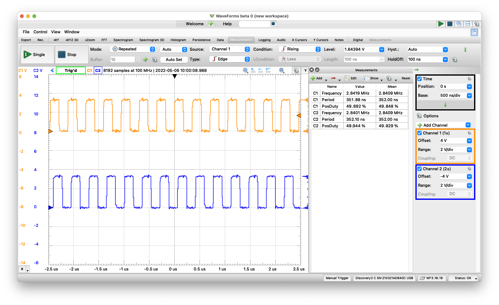
Mecrisp Forth running tasks
To be tested#
- C++ (Arduino) on the RP2040